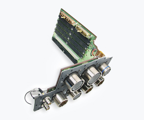
Aquacon Hermetic Connectors
Contact:
Description:
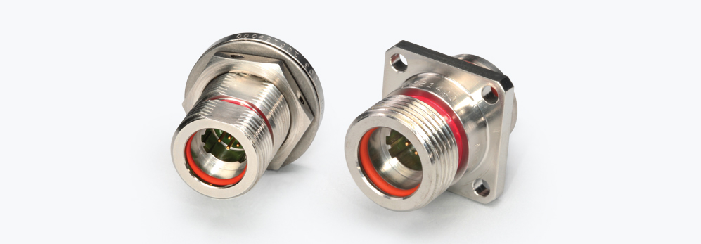
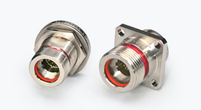
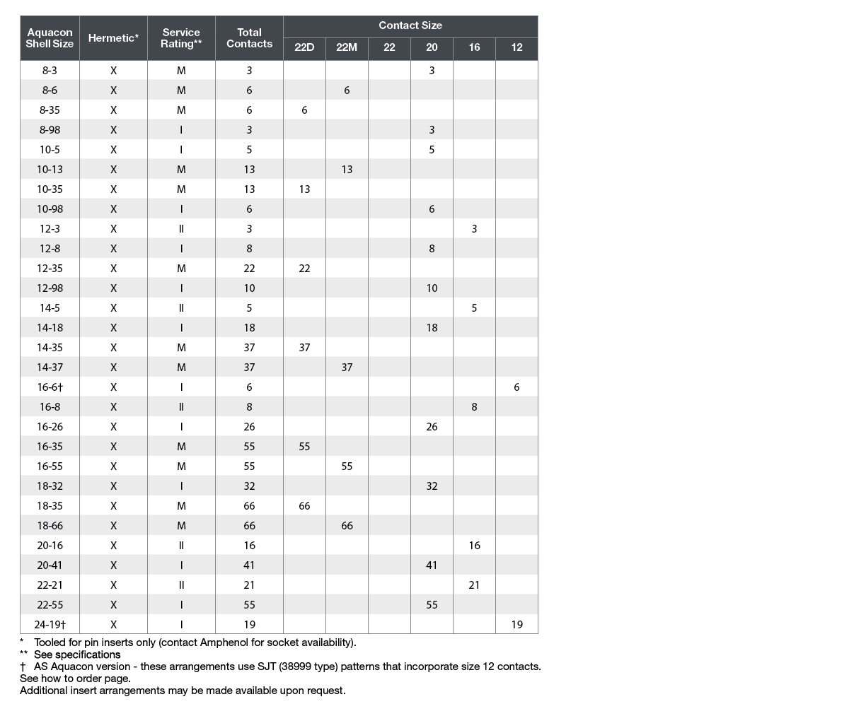
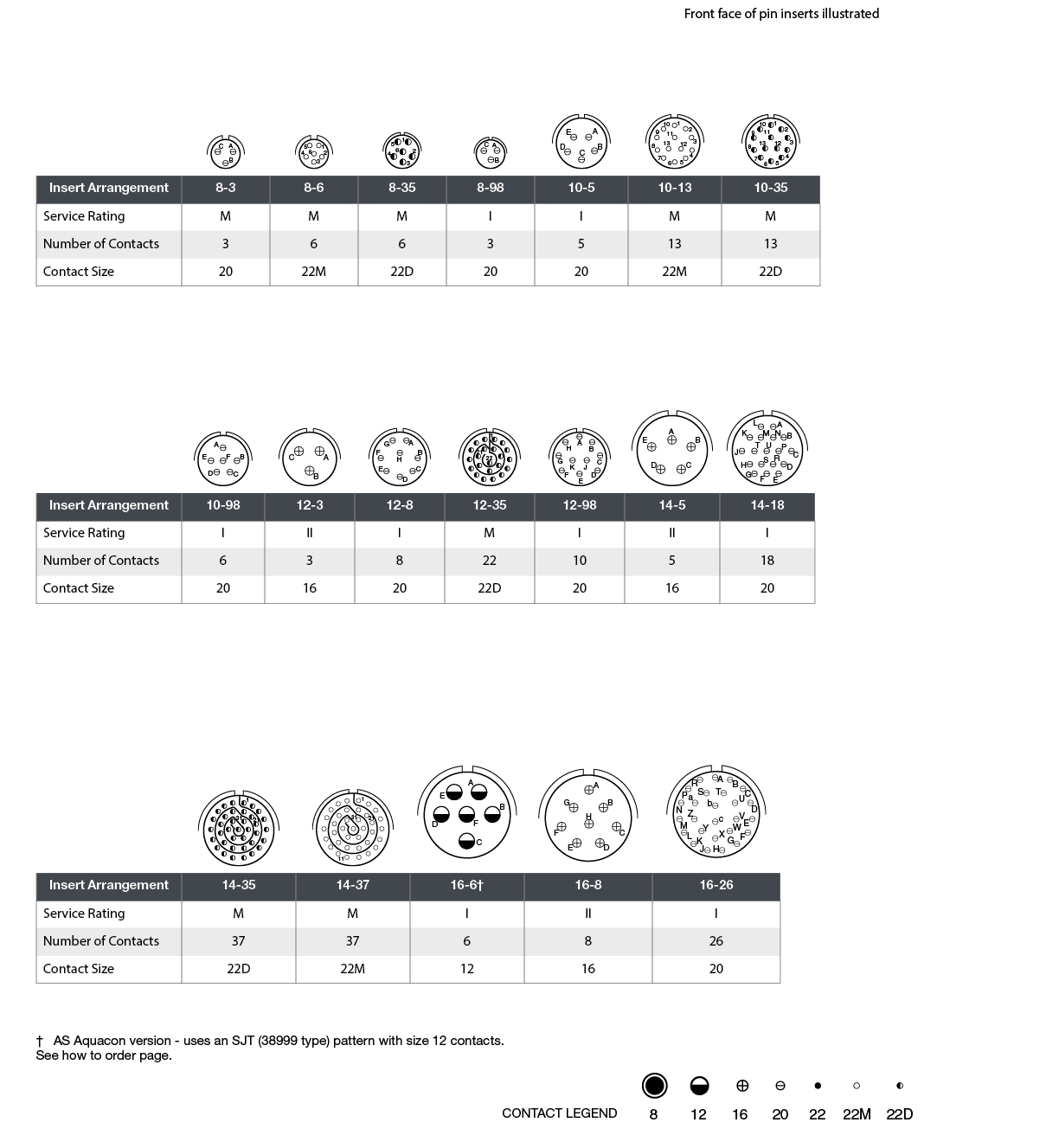
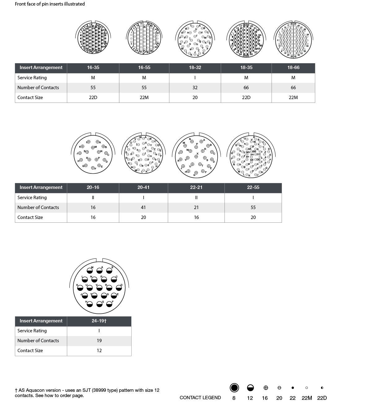
Amphenol Aquacon hermetic connectors are engineered to resist the corrosive environments encountered with oceanic or fluid immersion applications while maintaining a waterproof seal. Specially designed type 316 stainless-steel shells resist corrosion and can withstand hydrostatic pressure. Positive threaded coupling "O" rings, and a color band visual indicator assure proper sealing and mating.
Features & Benefits:
- Corrosion resistant aluminum bronze coupling nut
- 316 stainless steel shell resists corrosion and provides a pressure withstanding connector
- Hermetic sealing rated 1x10⁻⁸ cc/sec helium
- How many Contacts?
Consider including a number of redundant contacts to accommodate any system developments you have planned for the future, or to comply with specified growth provisions. - What are the electrical requirements?
Work out a steady state and peak requirement for both the current and voltage. - Will your Glass-to-Metal Sealing be under any pressure?
Depending on the medium (for example, oil, water, or a vacuum) there may be a pressure differential to consider. Glass-to-Metal Sealing (GTMS) can be supplied in multi-pin preforms or, for high pressure applications in individual glass beads. - How will your GTMS be attached?
Will it be secured with a standard O-ring, for example, or welded in place? - What are your cable interface requirements?
Be sure to include any instructions for screen termination, potting requirements, and/or cable strain relief. - Do you require custom functionality?
If you have any specific requirements, such as electromagnetic compatibility (EMC) filters or printed circuit board (PCB) mounting, make sure they are included in your design specification. - What are your plating requirements?
We offer a wide range of in-house plating options, including tin, nickel, and hard and soft gold. We can also customize the plating to meet any special requirements. Note that gold-plated solder contacts should either be desoldered before installation or appropriate plating thickness specified, to avoid solder embrittlement. - Are there any environmental factors?
If your application will be operating in a harsh or hostile environment (exposed to shock, vibration, thermal changes or extreme temperatures, for example) these will need to be factored into the design. - What are the qualification requirements?
If qualification tests are required, these should be discussed and specified during the design phase. We are able to perform most qualification tests on the appropriate levels of assembly. - What testing will you need?
Examples include leak testing, pressure testing, and geometrical and electrical testing; including breakdown, voltage, and insulation resistance of finished parts. - Cabling and wiring too?
If you would like to extend your brief to include your cabling and wiring requirements, we can address those as well.
Molding
The suggested method of assembly to cable for Aquacon plugs and cable connecting receptacles is molding. The mold sealing diameter has been designed to use a common mold for both plug and receptacle in the given shell size.
Sealing
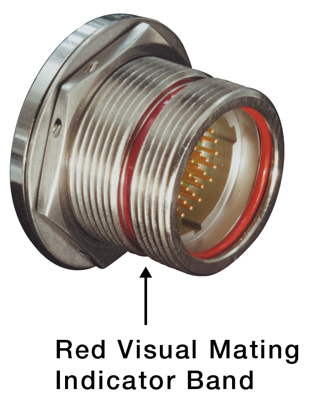
In a mated condition, the red visual mating indicator band must be fully concealed by the plug coupling nut to assure to reliable, pressure rated sealed joint. Failure to fully tighten the coupling nut may allow leakage through the main joint seal. The red visual mating indicator is so located that only a full and proper mating of the plug and receptacle will cause the indicator to be fully hidden by the plug coupling nut.
Mounting Surfaces
The integrity of an “O” ring hydrostatic shell is dependent upon the flatness of the surface on which the receptacle is mounted. Surface finishes of 23 microns or less are recommended for “O” ring sealing areas when jam nut or through bulkhead receptacles are mounted.
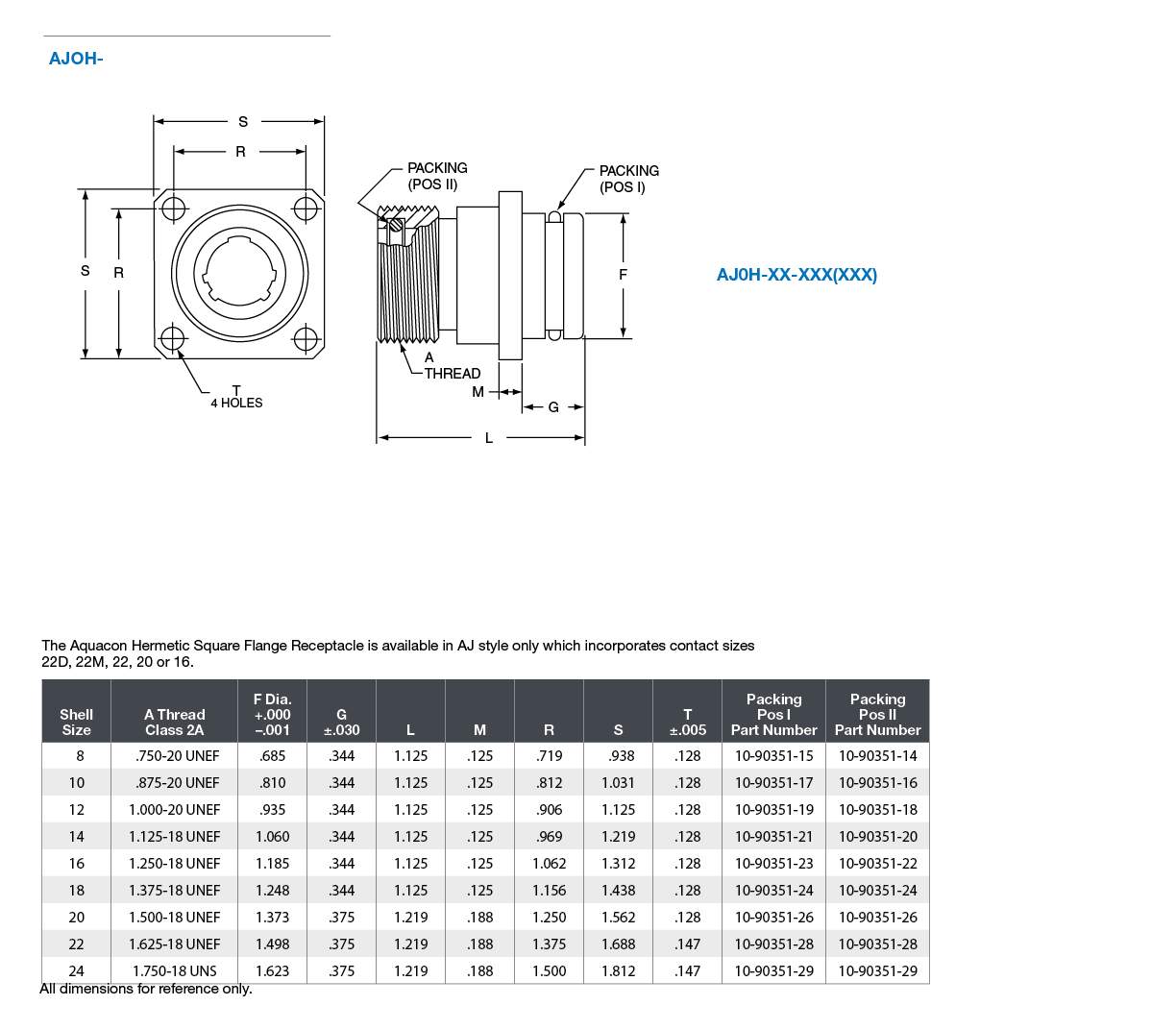
Receptacle "O" Ring Racking Number Requirements ARP 568 Uniform Dash Number
| Shell Size | Main Joint Seal | Shell to Mounting Surface Seal |
| Jam Nut | ||
| 8 | ARP-014 | ARP-019 |
| 10 | ARP-016 | ARP-021 |
| 12 | ARP-018 | ARP-023 |
| 14 | ARP-020 | ARP-025 |
| 16 | ARP-022 | ARP-027 |
| 18 | ARP-024 | ARP-029 |
| 20 | ARP-026 | ARP-030 |
| 22 | ARP-028 | ARP-031 |
| 24 | ARP-029 | ARP-032 |
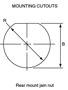
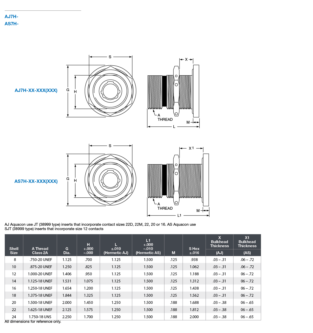
| Shell Size | B +.010 -.000 |
R |
| 8 | .705 | .759 |
| 10 | .830 | .884 |
| 12 | .955 | 1.007 |
| 14 | 1.080 | 1.134 |
| 16 | 1.205 | 1.259 |
| 18 | 1.330 | 1.384 |
| 20 | 1.455 | 1.507 |
| 22 | 1.580 | 1.634 |
| 24 | 1.705 | 1.759 |
Wire and Cable Preparation
Cut wire or cable to desired length. Strip insulation from end of wire in accordance with the following table. Hot wire stripping methods are recommended. Avoid nicking or cutting wire strands.
Wire Strip Length in Inches:
| Contact Type | Contact Size | |||||
| 22M | 22D | 22 | 20 | 16 | 12 | |
| Solder | 1/8 | - | 1/8 | 5/32 | 5/32 | |
| Crimp | 1/8 - 5/32 | 1/8 - 5/32 | ||||
Solder Contact Termination:
- Clean conductors and pre-tin with a good grade 60/40 tin-lead solder to 1/16 inch.
- Pre-tin contact solder well.
- With connector in a suitable holding device, solder wells facing operator, and the cutaway portion of the wells up, insert pre-tinned conductor into contact well. Apply heat to closed side of wire well to make joint. Remove heat and allow joint to cool.
- A resistance soldering unit of approximately 125 watts is recommended. If a soldering iron is used, do not exceed 20 watts for size 22M, 22D and 22 contacts; 80 watts for size 20: and 150 watts for size 16 and 12 contacts.
- Wipe or brush excess flux from terminations.
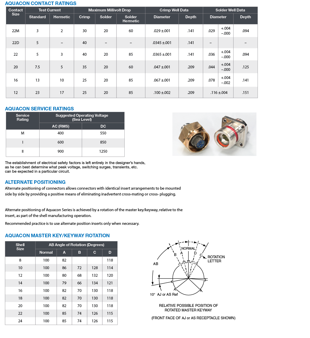
Aquacon Contact Ratings
| Contact Size | Test Current | Maximum Millivolt Drop | Crimp Well Data | Solder Well Data | ||||||
| Standard | Hermetic | Crimp | Solder | Solder Hermetic | Diameter | Depth | Diameter | Depth | ||
| 22M | 3 | 2 | 30 | 20 | 60 | .029±.001 | .141 | .029 | +.004 -.000 |
.094 |
| 22D | 5 | - | 40 | - | - | .0345±.001 | .141 | - | - | |
| 22 | 5 | 3 | 40 | 20 | 85 | .0365±.001 | .141 | .036 | +.004 -.000 |
.094 |
| 20 | 7.5 | 5 | 35 | 20 | 60 | .047±.001 | .209 | .044 | +.004 -.000 |
.125 |
| 16 | 13 | 10 | 25 | 20 | 85 | .067±.001 | .209 | .078 | +.004 -.002 |
.141 |
| 12 | 23 | 17 | 25 | 20 | 85 | .100±.002 | .209 | .116±.004 | .151 | |
Aquacon Service Ratings
| Service Rating | Suggested Operating Voltage (Sea Level) | |
| AC (RMS) | DC | |
| M | 400 | 550 |
| I | 600 | 850 |
| II | 900 | 1250 |
The establishment of electrical safety factors is left entirely in the designer’s hands, as they can best determine what peak voltage, switching surges, transients, etc. can be expected in a particular circuit.
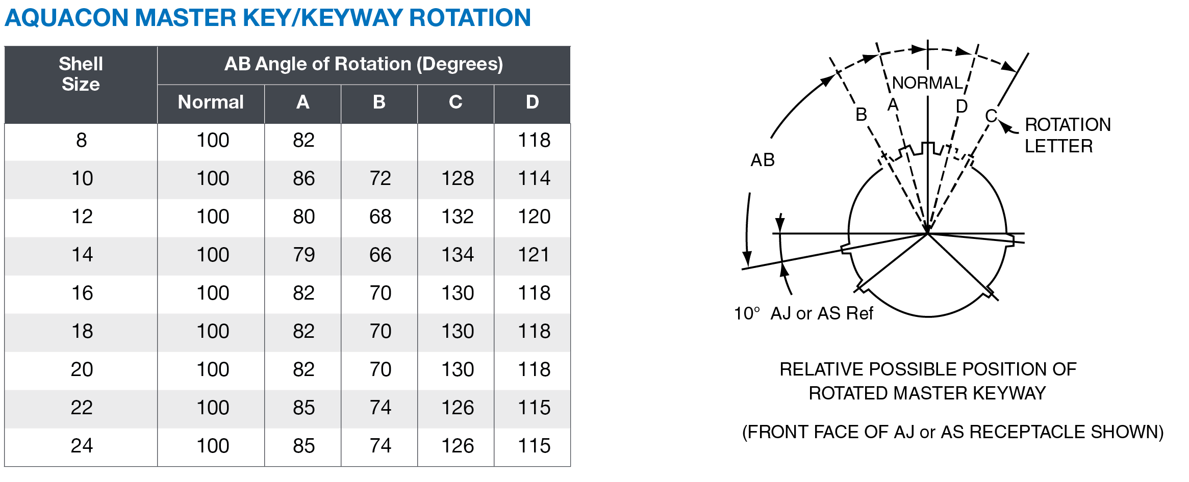
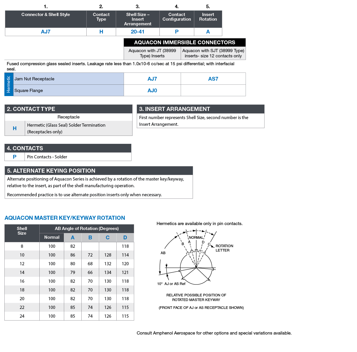
Alternate positioning of connectors allows connectors with identical insert arrangements to be mounted side by side by providing a positive means of eliminating inadvertent cross-mating or cross- plugging. Alternate positioning of Aquacon Series is achieved by a rotation of the master key/keyway, relative to the insert, as part of the shell manufacturing operation. The recommended practice is to use alternate position inserts only when necessary.
