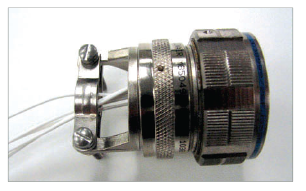
2M805 Tri-Start Threaded Coupling Micro-Miniature Connectors

Product 2M805 Tri-Start Threaded Coupling Product 2M805 Tri-Start Threaded Coupling

Contact:

Peter Cook
Product Manager
+1 (607) 563-5519
pcook@amphenol-aao.com

Description:

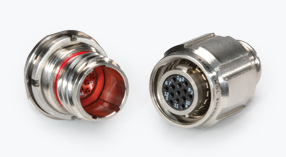
2M805 micro 38999 connectors are the evolution of the mil-standard circular. Designed to meet the same harsh environmental requirements of D38999, they were developed to make scaling-down existing technology easy and risk-free. Your systems are getting smaller, lighter, and faster; so why wouldn’t your interconnect do the same? Less than half the size and weight of their 38999 predecessors, you can reduce size, reduce space, and reduce cost… but never reduce your expectations.
Features & Benefits:

  • Tri-Start fast coupling
  • Excellent EMI shielding
  • Superior vibration resistance
  • Waterproof
  • Nickel-plated ground spring
  • High Speed Options Available
2M805 vs. D38999 Comparison

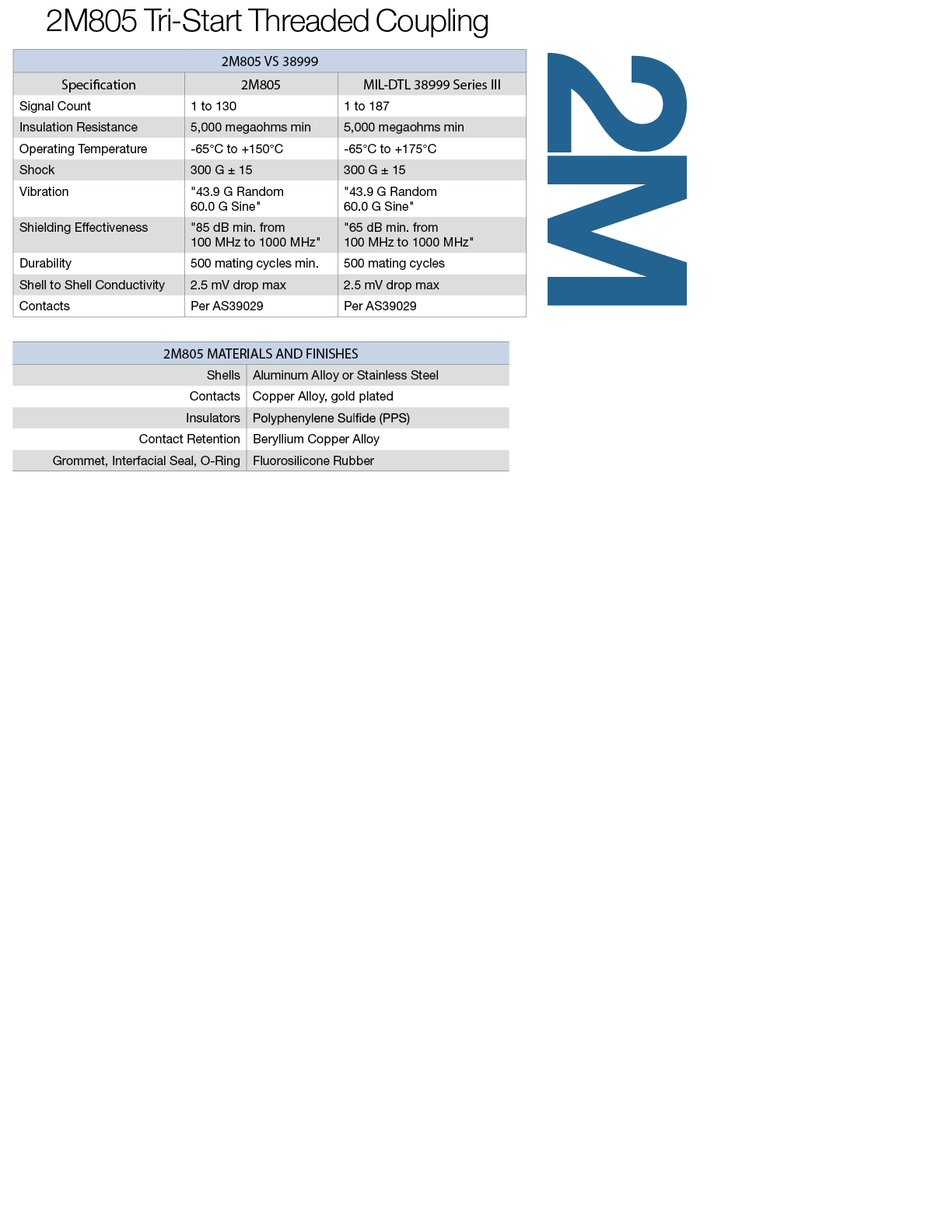
Performance Specifications


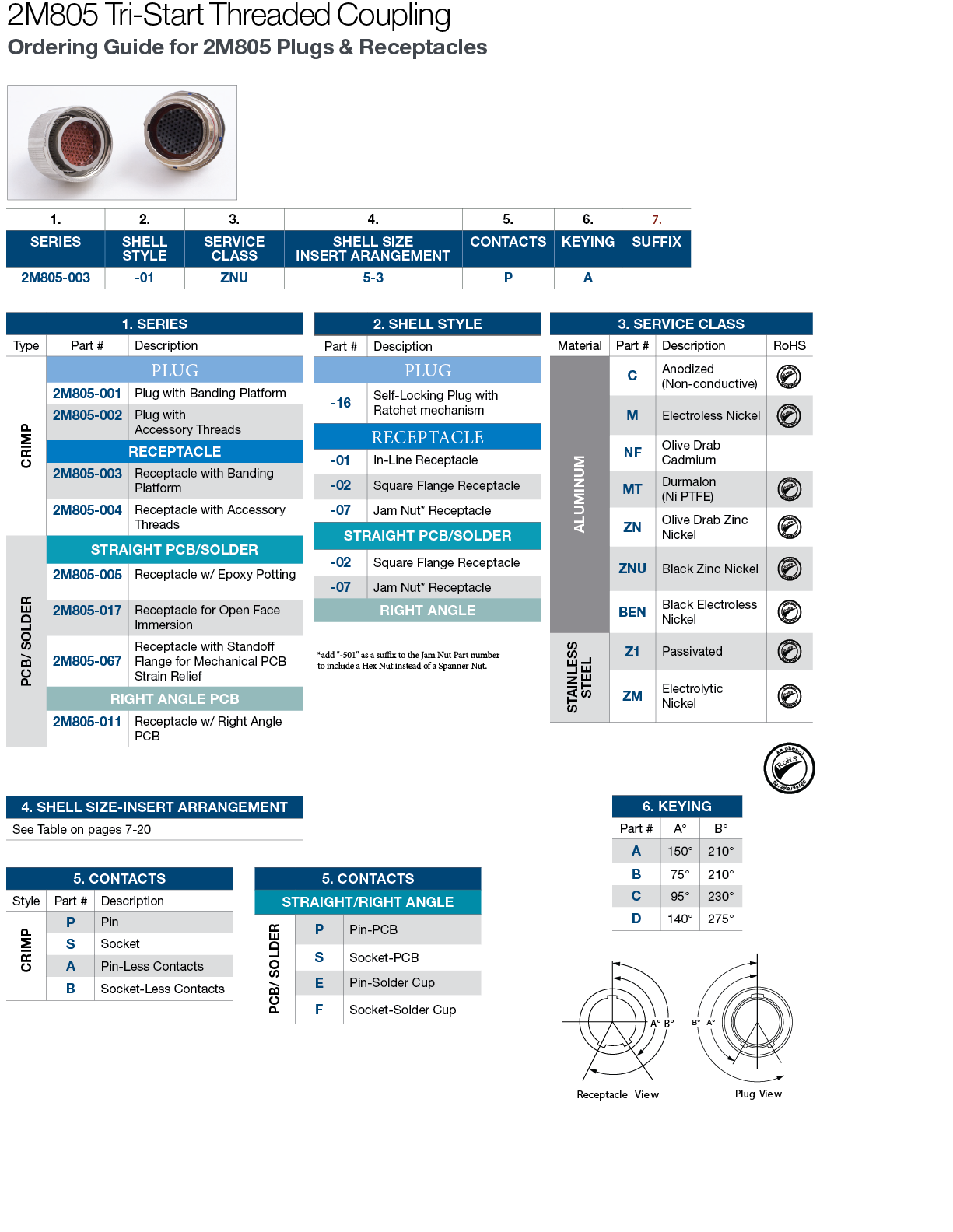
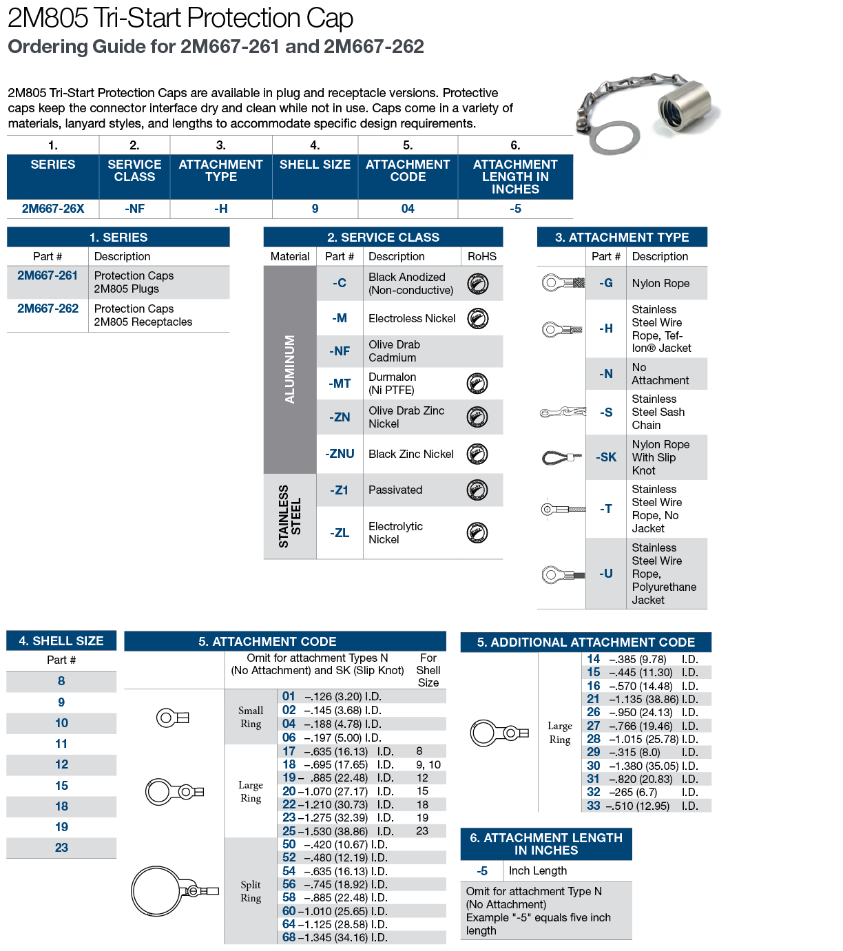
How to Order Guides


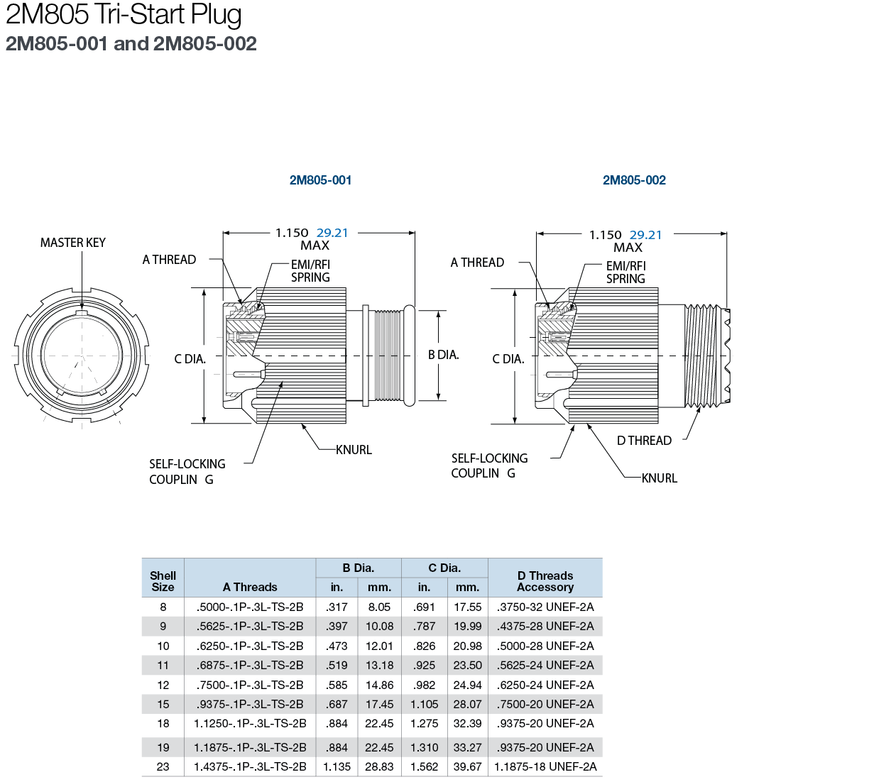
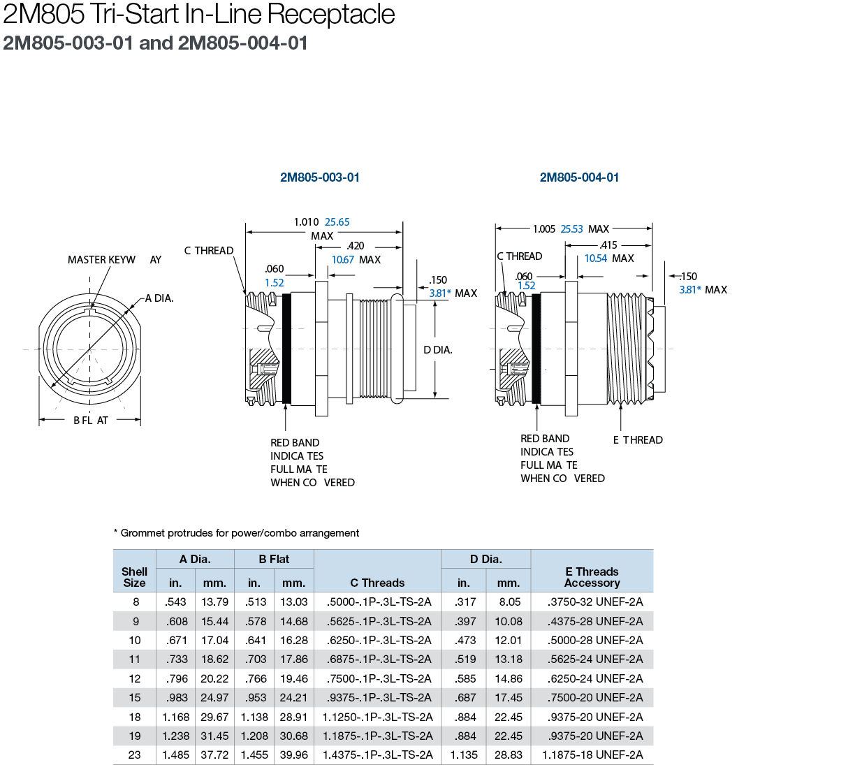
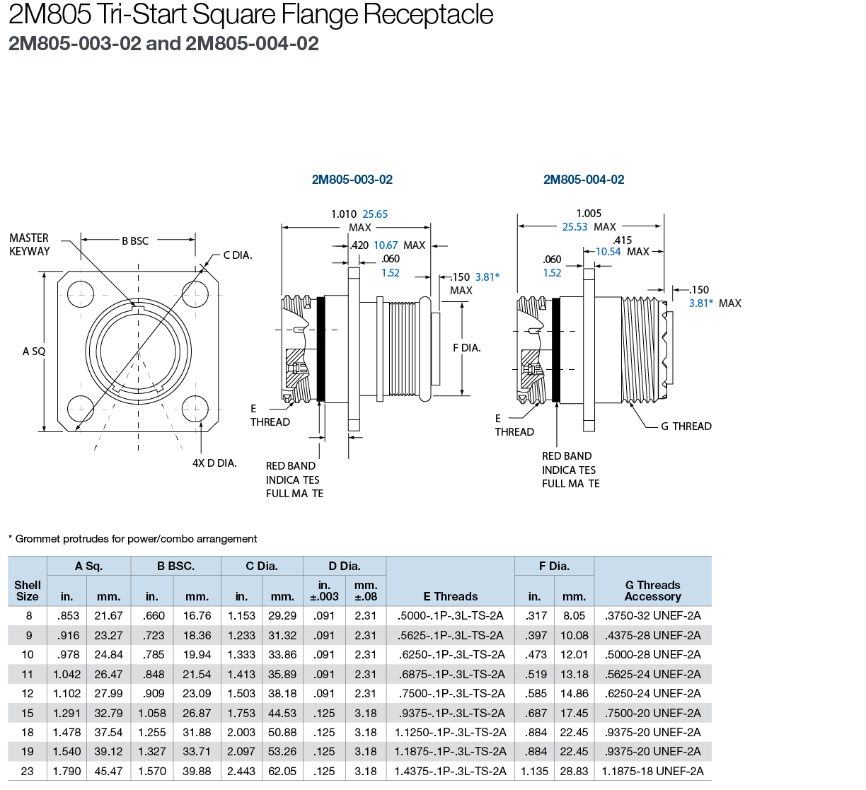
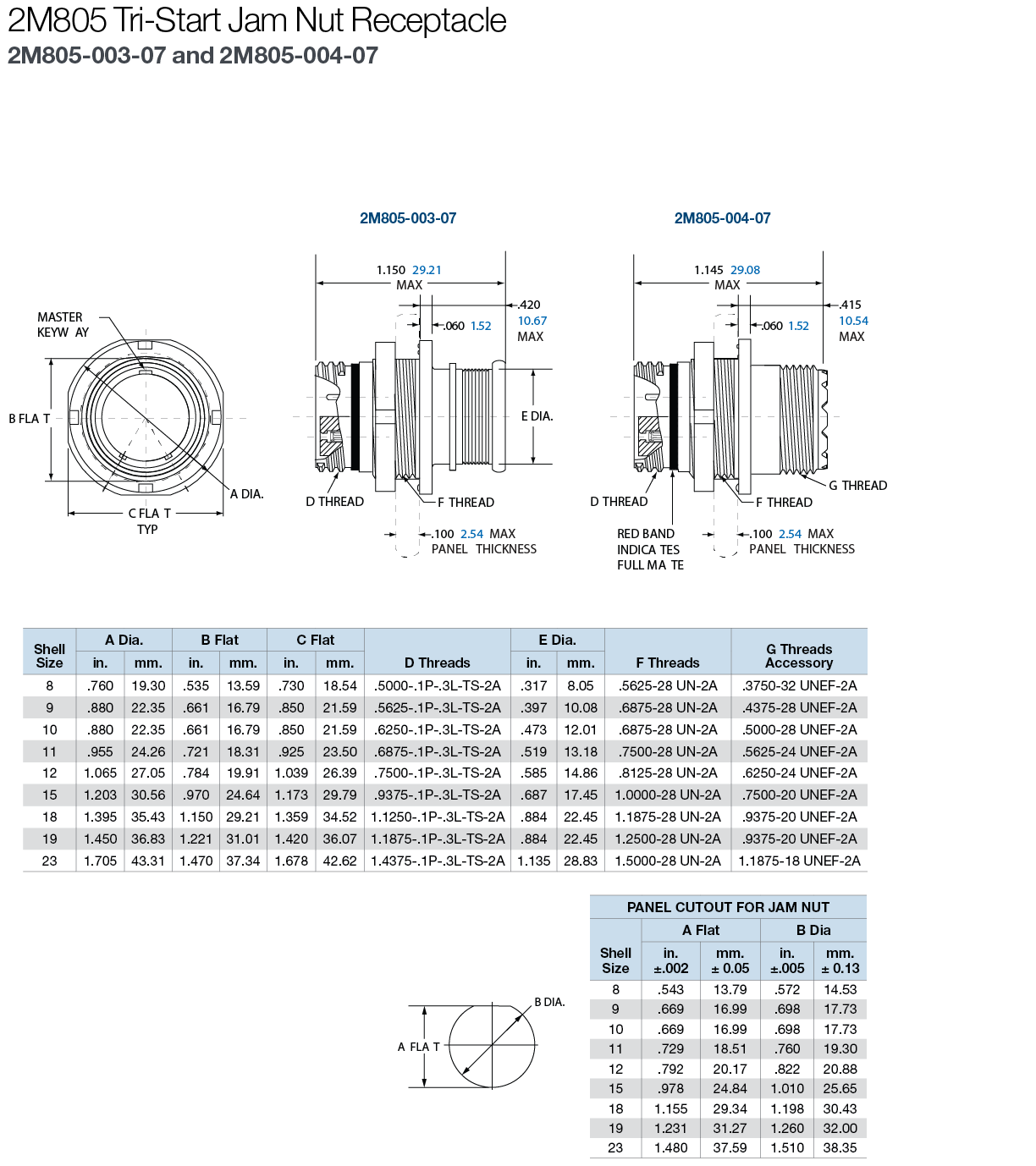
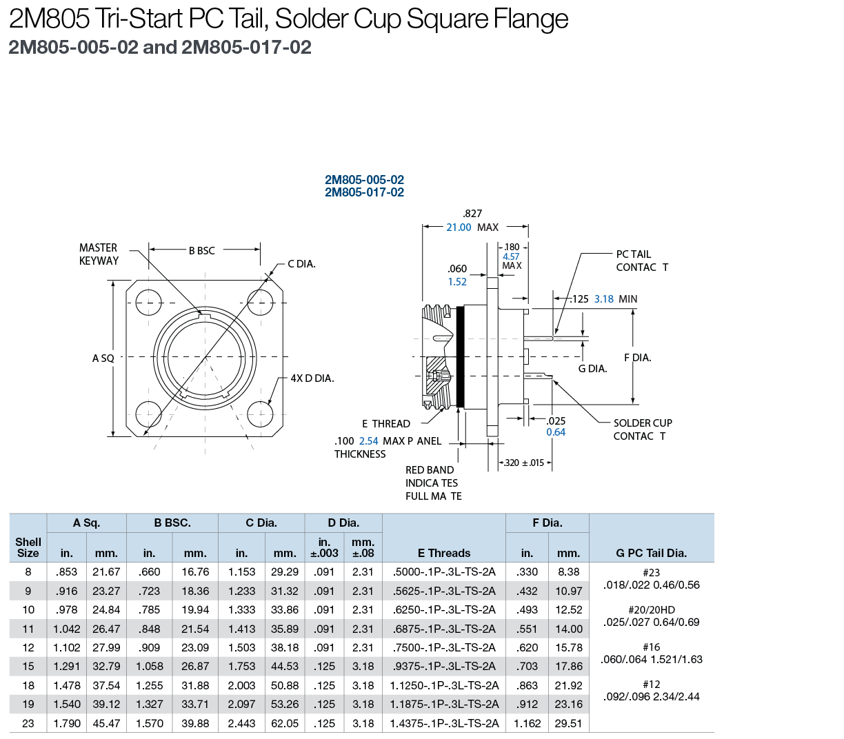
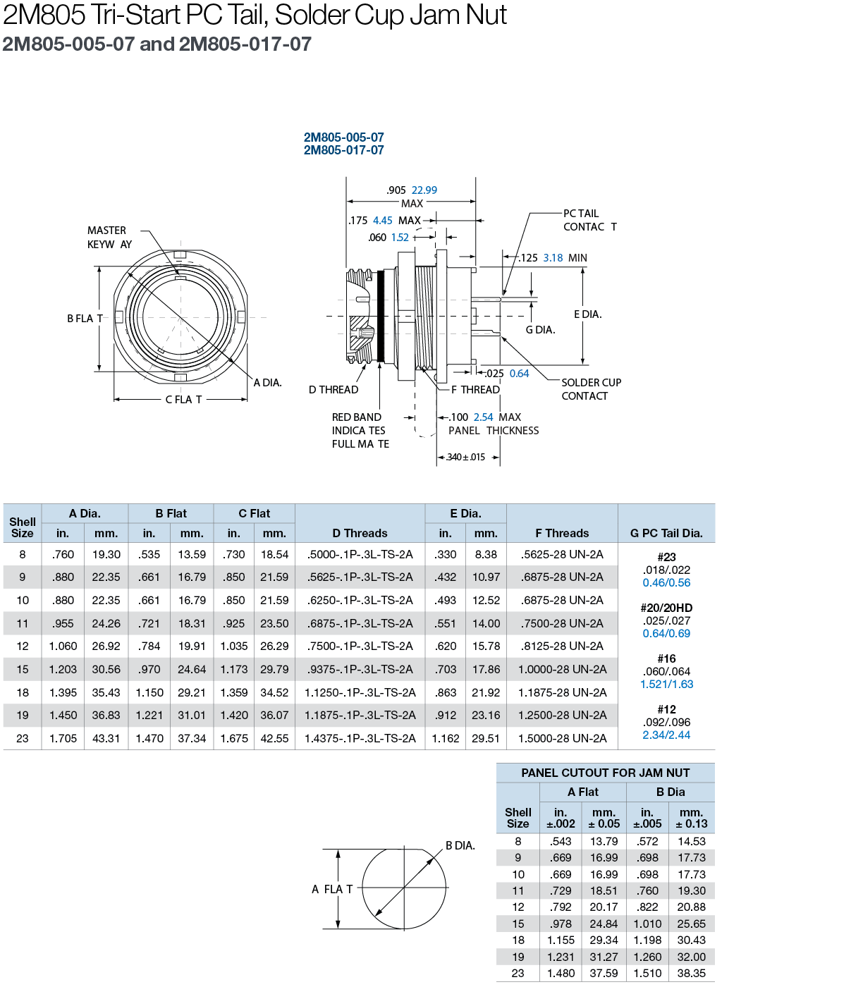
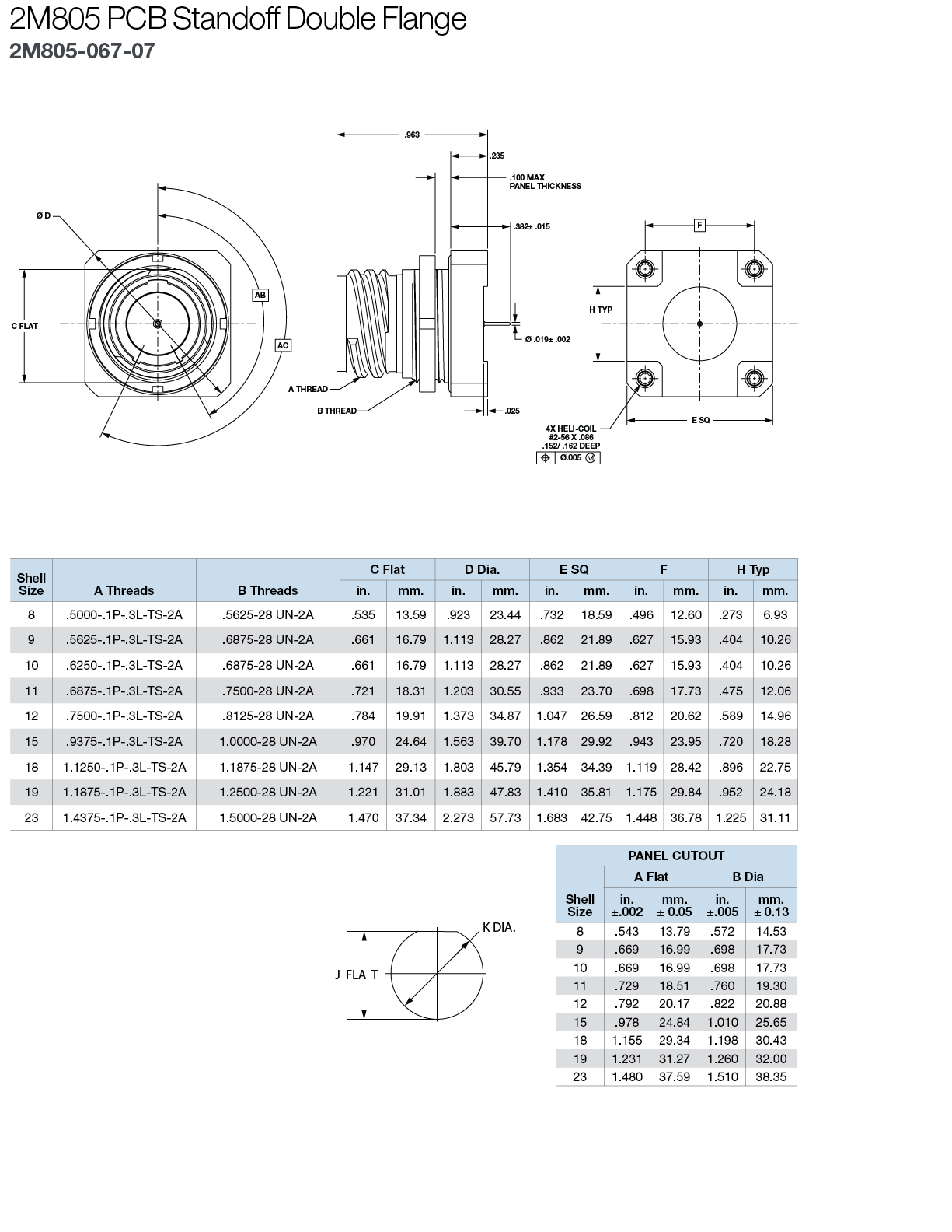
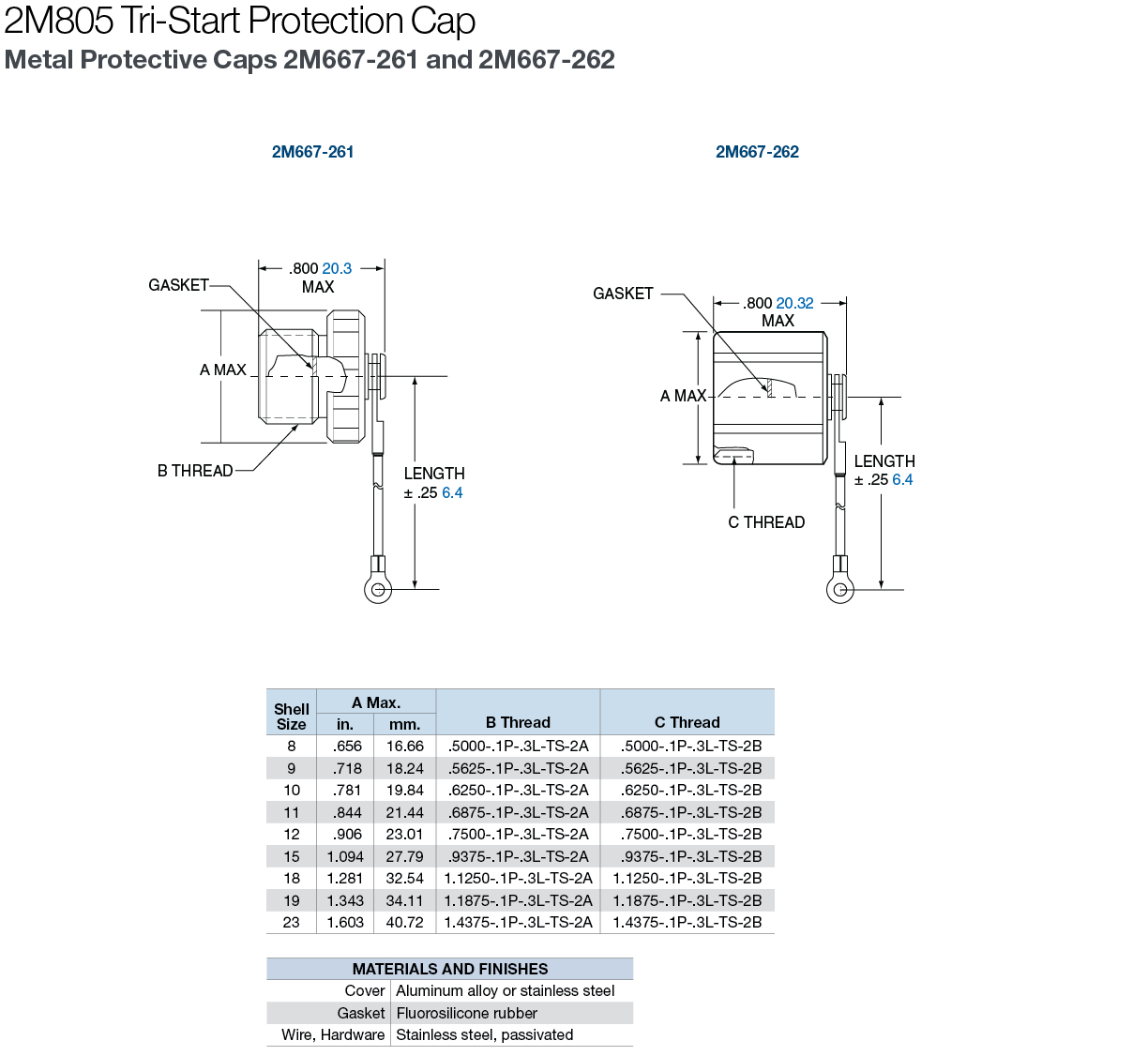
Dimensions


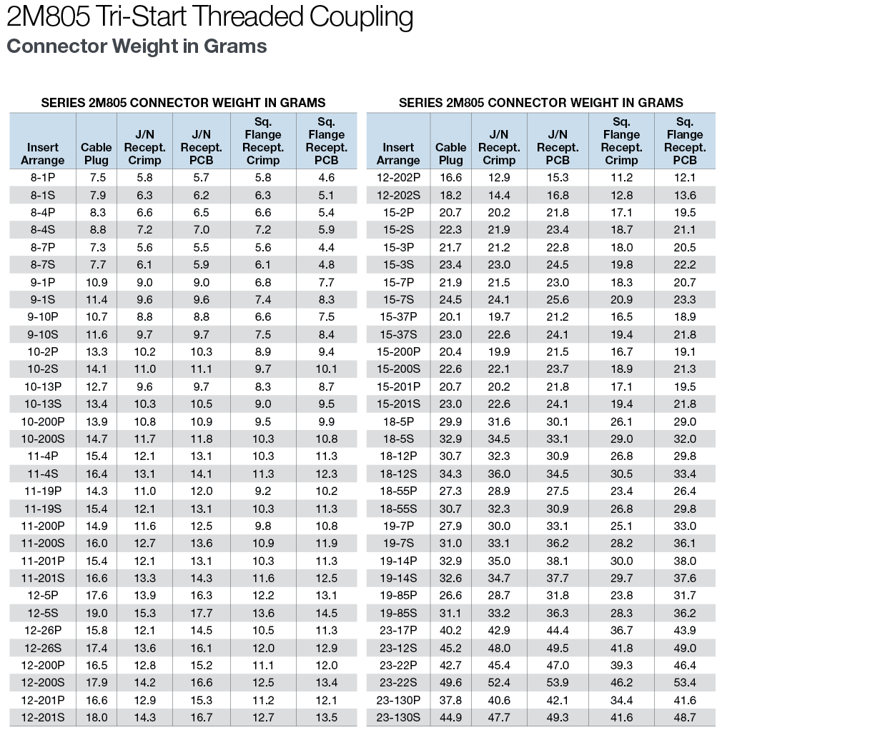
Connector Weights

Insert Arrangements

Straight PCB Footprints

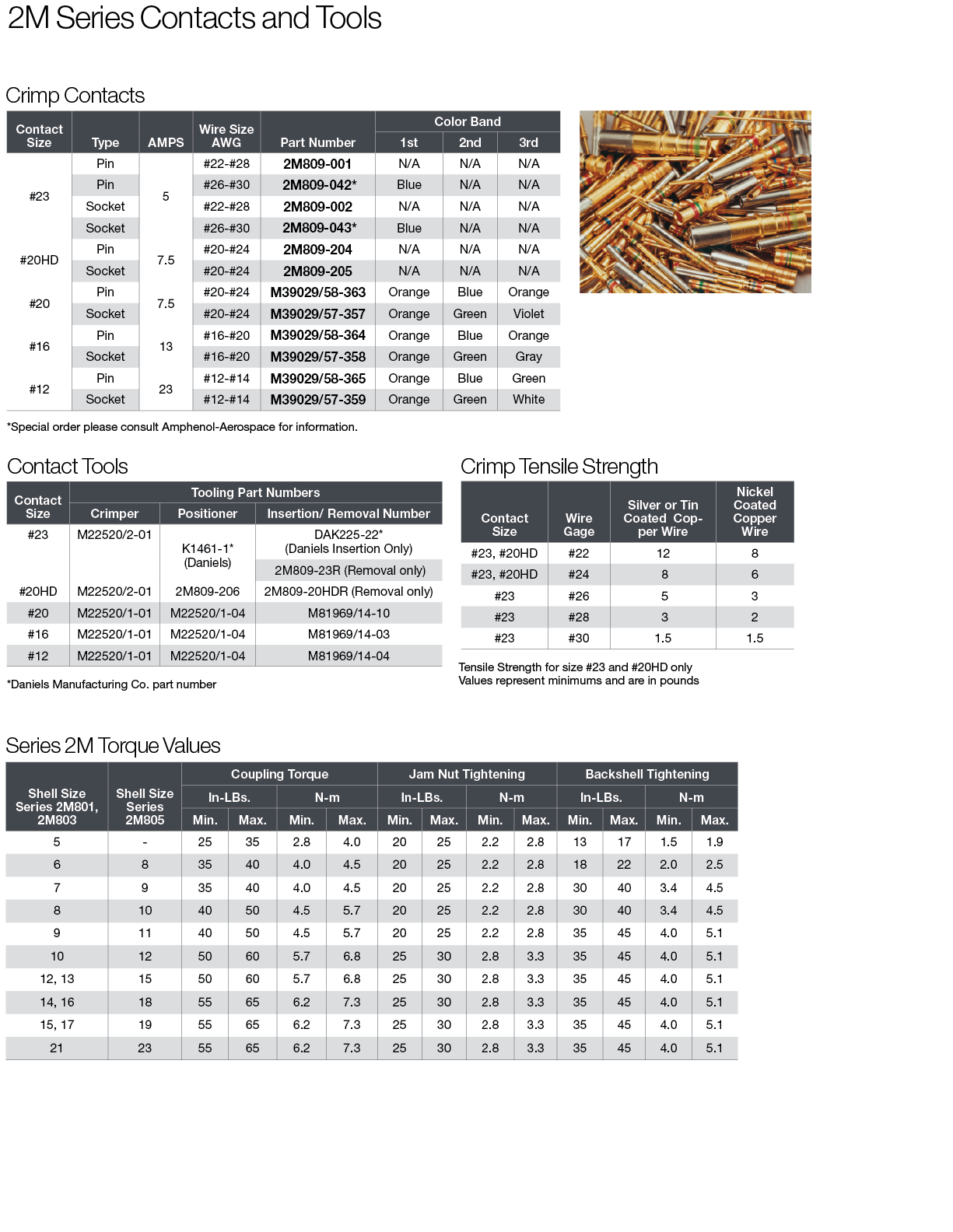
Contacts and Tool Information

Size and Weight Comparison Charts


Weight :

2M805 D38999  D38999 Aluminum D38999 Composite
Layout Number of Contacts Weight  Layout  Number of Contacts Weight % Weight Savings Weight % Weight Savings
8-7 7 #23 13.4 9-35 6 #20 26.3 49% 19.9 33%
10-13 13 #23 23.0 11-35 13 #22D 35.7 36% 26.8 14%
11-19 19 #23 26.4 13-35 19 #22D 50.7 48% 38.5 31%
12-26 26 #23 29.4 17-26 26 #20 58.5 50% 62.6 53%
15-37 37 #23 42.7 15-35 37 #22D 72.1 41% 57.4 26%
18-55 55 #23 59.6 17-35 55 #22D 81.6 27% 65.6 9%
19-85 85 #23 59.8 21-35 85 #22D 119.7 50% 99.1 40%
23-130 130 #23 85.5  25-35 128 #22D 159.3 46% 136.6 37%


Size : 

2M805 D38999  Maximum Plug Diameter Maximum Jam Nut Receptacle Diameter
Layout  Layout 2M805 D38999 % Reduction 2M805 D38999 % Reduction
in mm in mm in mm in mm
8-7 9-35 .707 17.96 .859 21.81 17% .775 19.69 1.201 30.51 35%
10-13 11-35 .804 20.42 .969 24.61 18% .895 22.73 1.386 30.50 35%
11-19 13-35 .933 23.70 1.141 28.98 20% .960 24.38 1.512 38.40 36%
12-26 17-26 .999 25.37 1.391 35.33 29% 1.075 27.31 1.764 44.81 39%
15-37 15-35 1.113 28.27 1.266 32.16 13% 1.218 30.86 1.638 41.61 26%
18-55 17-35 1.308 33.02 1.391 35.33 7% 1.404 35.66 1.764 44.81 20%
19-85 21-35 1.328 33.73 1.625 41.27 19% 1.465 37.21 2.075 52.71 29%
23-130 25-35 1.577 40.06 1.875 47.63 16% 1.720 43.69 2.323 59.00 26%


Weight : 

2M801 D38999  D38999 Aluminum D38999 Composite
Layout Number of Contacts Weight  Layout  Number of Contacts Weight % Weight Savings Weight % Weight Savings
5-3 3 7.9 9-98 3 25.3 69% 19.9 60%
6-7 7 9.8 9-35 6 26.3 63% 19.9 51%
9-19 19 18.8 13-35 22 50.7 63% 38.5 51%
13-37 37 36.0 15-35 37 72.1 50% 57.4 37%
16-55 55 49.8 17-35 55 81.6 39% 65.6 24%
17-85 85 54.3 21-35 79 119.7 55% 99.1 45%
21-130 130 68.7 25-35 128 159.3 57% 136.6 50%

Note: Weights shown include contacts and represent a mated pair of plug and jam nut receptacle. Weights are in grams.


Size : 

2M801 D38999  Maximum Plug Diameter Maximum Jam Nut Receptacle Diameter
Layout  Layout 2M801 D38999 % Reduction 2M801 D38999 % Reduction
in mm in mm in mm in mm
5-3 9-98 .540 13.72 .859 21.82 37% .575 14.61 1.204 30.58 52%
6-7 9-35 .600 15.24 .859 21.82 30% .635 16.13 1.204 30.58 47%
9-19 13-35 .810 20.57 1.156 29.36 30% .830 21.08 1.516 38.51 45%
13-37 15-35 1.050 26.67 1.281 32.54 18% 1.078 27.38 1.641 41.68 34%
16-55 17-35 1.240 31.50 1.406 35.71 12% 1.264 32.11 1.766 44.86 28%
17-85 21-35 1.300 33.02 1.641 41.68 21% 1.325 33.66 2.078 52.78 36%
21-130 25-35 1.550 39.37 1.890 48.01 18% 1.625 41.28 2.323 59.00 30%

Note: Weights shown include contacts and represent a mated pair of plug and jam nut receptacle. Weights are in grams.

Assembly Instructions

Wire Stripping

  1. Strip wire to required length. When using hot wire stripping, do not wipe melted insulation material on wire strands; with mechanical strippers do not cut or nick strands.
  2. See Table 1 for proper finished outside wire dimensions.
  3. Twist strands together to form a firm bundle.
  4.  Insert stripped wire into contact applying slight pressure until wire insulation butts against wire well. Check inspection hole to see that wire strands are visible. If there are strayed wire strands, entire wire end should be re-twisted. When wire is stripped and properly installed into contact, the next step is to crimp the wire inside the contact by using the proper crimping tool.

Crimping

  1. Insert stripped wire into contact crimp pot. Wire must be visible through inspection hole.
  2. Using correct crimp tool and locator, cycle the tool once to be sure the indentors are open, insert contact and wire into locator. Squeeze tool handles firmly and completely to insure a proper crimp. The tool will not release unless the crimp indentors in the tool head have been fully actuated.
  3. Release crimped contact and wire from tool. Be certain the wire is visible through inspection hole in contact.

Contact Insertion

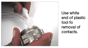
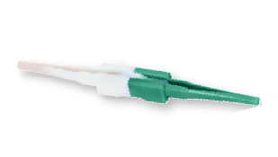
Note: All plastic tools are double-ended. The colored side is the insertion tool and the white side is the removal tool.
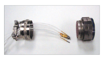
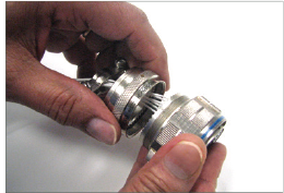
  1. First remove hardware from the plug and receptacle and slide the hardware over wires in proper sequence.
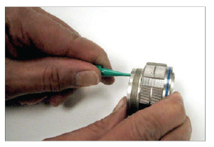
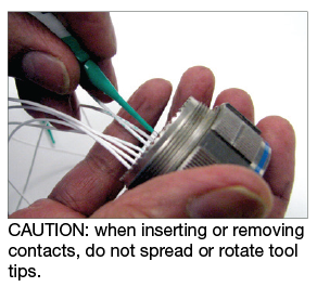
  2. Use proper plastic or metal insertion tool for the corresponding contact. Slide correct tool (with plastic tool use colored end) over wire insulation and slide forward until tool bottoms against rear contact shoulder.
  3. Next, align the tool and contact up to the properly-identified cavity at rear of connector plug. Use firm, even pressure; do not use excessive pressure. It is recommended to start at the center cavity. Contact must be aligned with grommet hole and not inserted at an angle. Push forward until contact is felt to snap into position within insert.
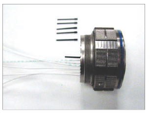
  4. Remove tool and pull back lightly on wire, making sure contact stays properly seated and isn’t dragged back with the tool. Repeat the operation with the remainder of contacts to be inserted, beginning with the center cavity and working outward in alternating rows.
  5. After all contacts are inserted, fill any empty cavities with wire sealing plugs.
  6.  Reassemble plug or receptacle hardware slide forward and tighten using connector pliers. Connector holding tools are recommended while tightening back accessories. When using strain relief, center wires at bar clamp. Slide clamp grommet into position and tighten clamp bar screws. When tightening screws, pressure should be applied in the same direction that clamp is threaded to rear threads of the connector. When not using clamp grommet, build up wire bundle with vinyl tape so clamp bar will maintain pressure on wires.

Contact Removal

  1. Remove hardware from plug or receptacle and slide hardware back along wire bundle.
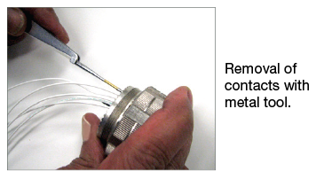
  2. Use proper plastic or metal removal tool for corresponding contact. Slide correct size tool over wire insulation.
  3. Insert plastic or metal removal tool into contact cavity until tool tips enter rear grommet and come to a positive stop. Hold tool tip firmly against positive stop on contact shoulder. Grip wire and simultaneously remove tool and contact. (On occasion, it may be necessary to remove tool, rotate 90° and reinsert.)


2M Micro38999 Catalog
The 2M Micro38999 Connector Series product line is designed for interconnect applications requiring high performance and reduced size and weight.
2M805 Qualification Test Summary Report
Defines the test samples, test sequences and test methods used to verify that Amphenol 2M805 Series of connectors meet industry standards for miniature ruggedized circular connectors.
Video Amphenol Aerospace 2M Connectors
Amphenol Aerospace 2M Connectors
2:38
2M Hermetic
The small and lightweight 2M Hermetic connector provides an exceptional airtight seal without sacrificing ruggedness and meets or exceeds most MIL-DTL-38999 environmental and performance requirements.
2M Filters
The versatility of standard 2M connectors with EMI protection to meet the demands of your application.
2M Accessories
Complete line of accessories for all 2M connectors
2M804 Push-Pull Quick-Disconnect
Ruggedized, push-pull miniature connectors with multiple options for soldier-worn applications.
2M803 1/4 Turn Bayonet Coupling
General purpose, bayonet-coupling miniature connectors for light-duty applications that require frequent disconnect.
2M801 Dual-Start Acme Threads
Dual-Start threaded miniature connectors for applications that require compatibility with existing technologies or cables.
Distributor?
Is FAI Required?
Have you ordered from us before?

Part Number
Min Qty
Max Qty
Target Price
Delivery Date
Add Part