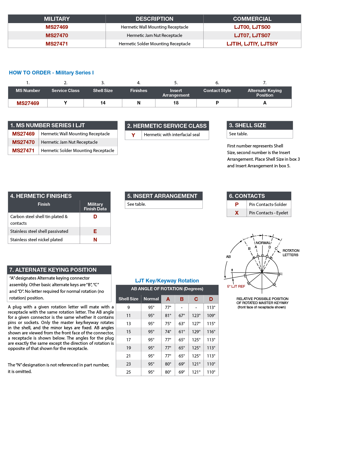
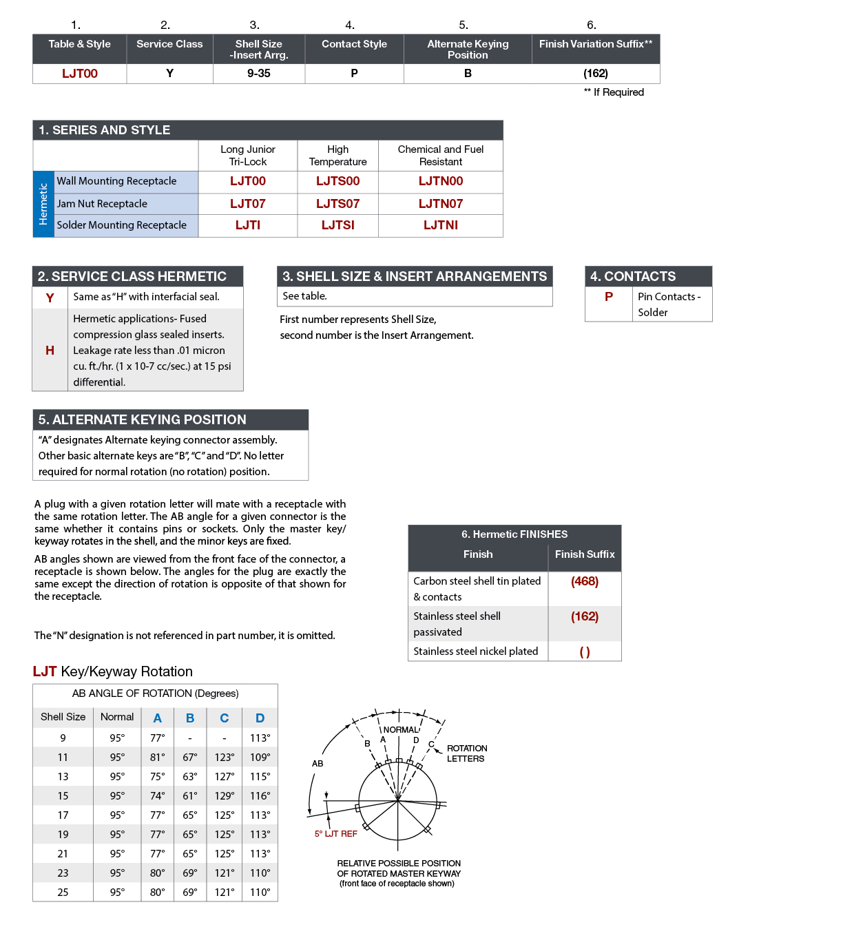
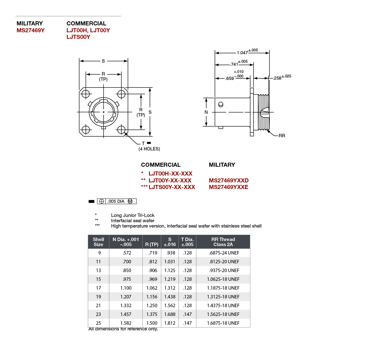
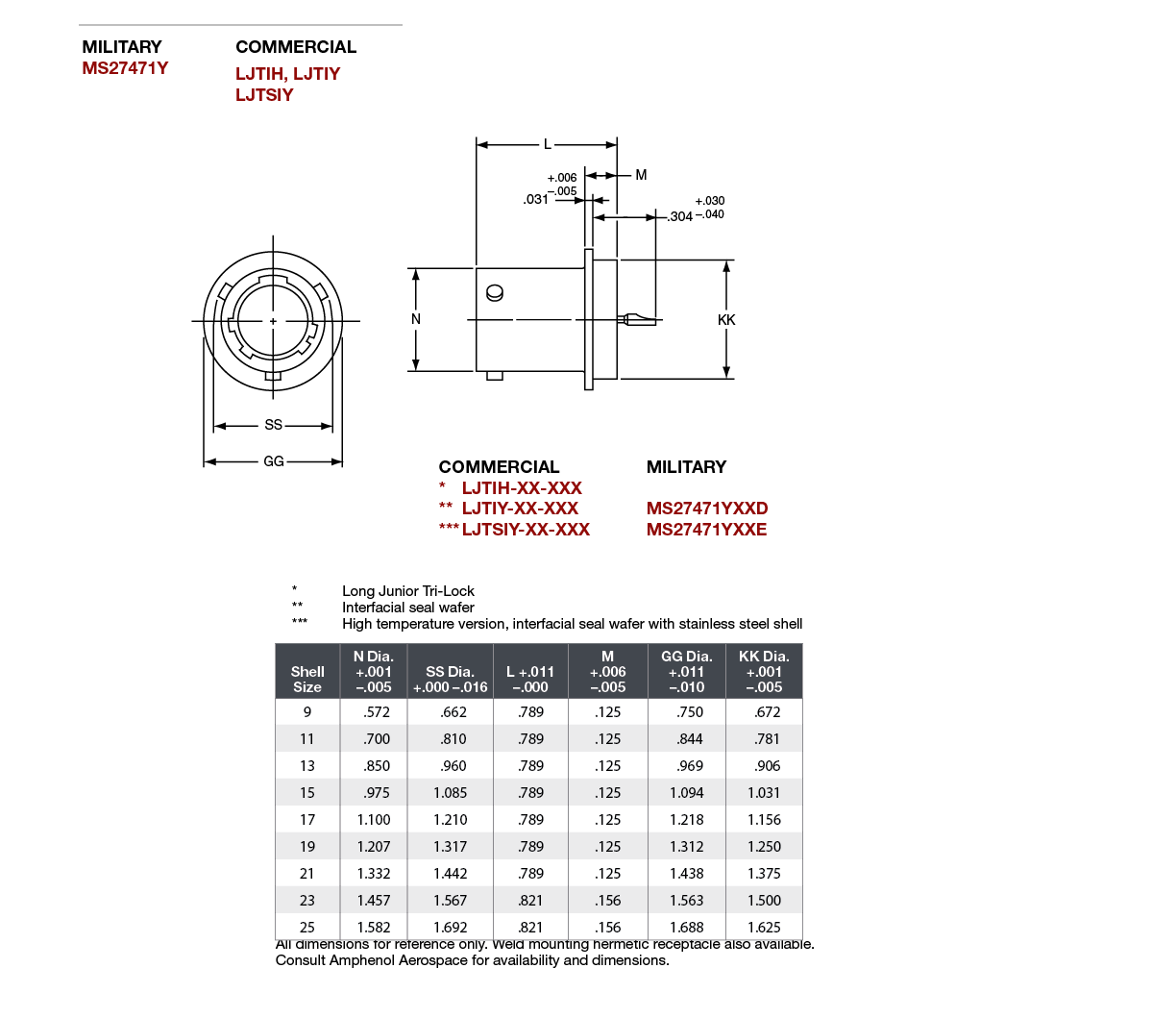
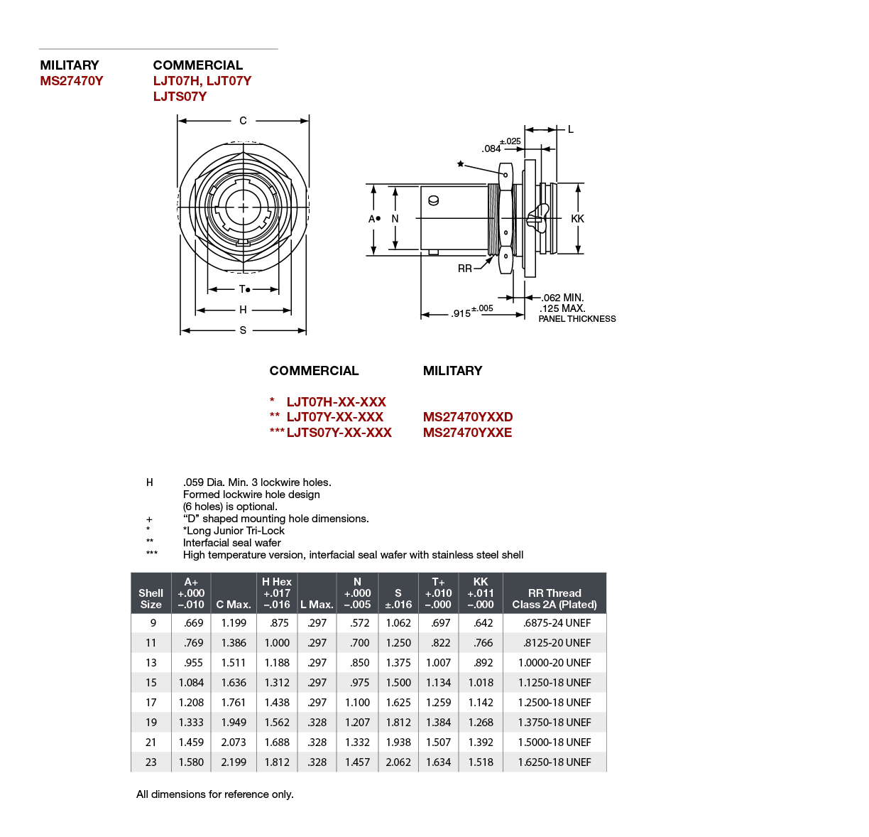
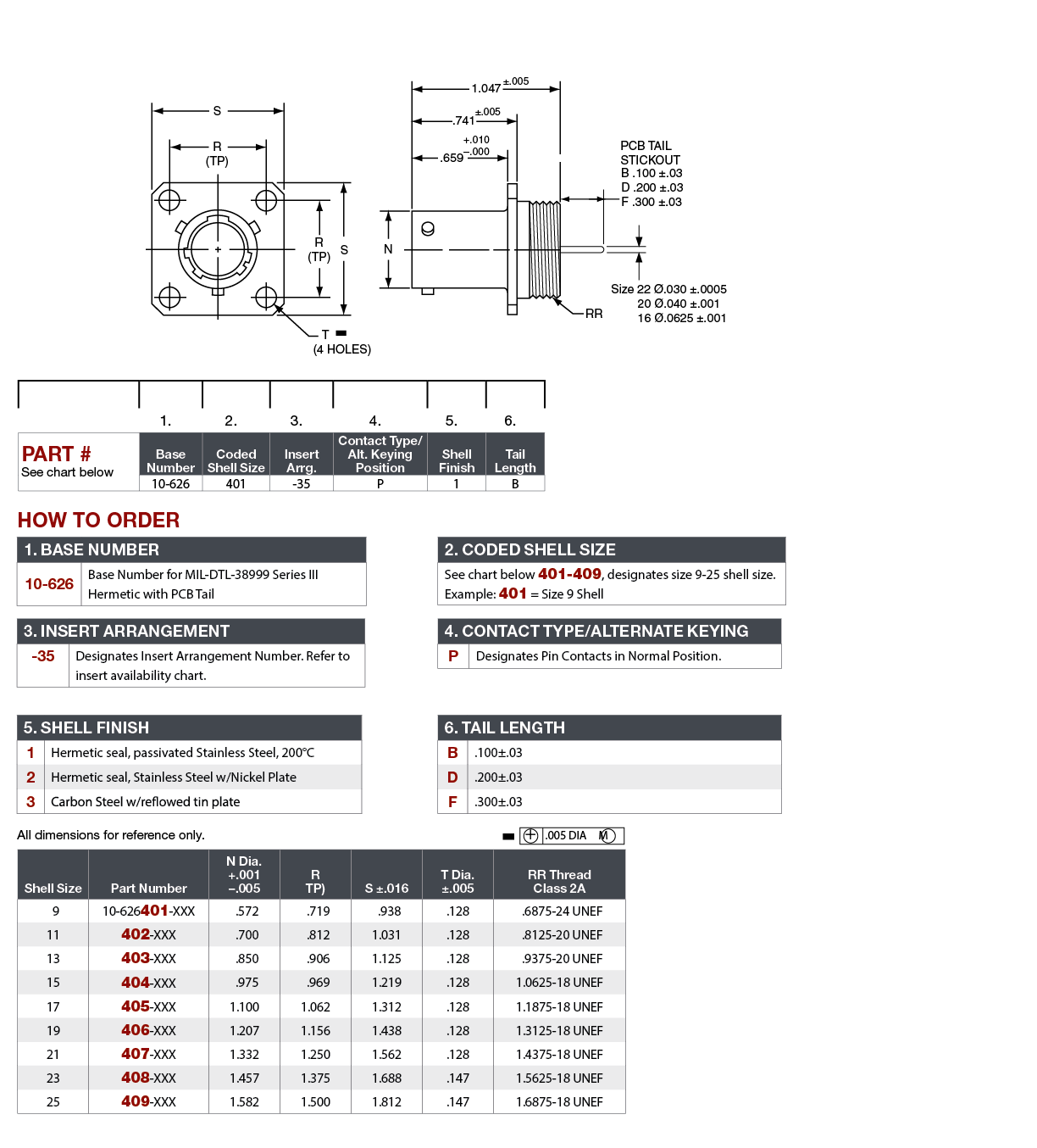
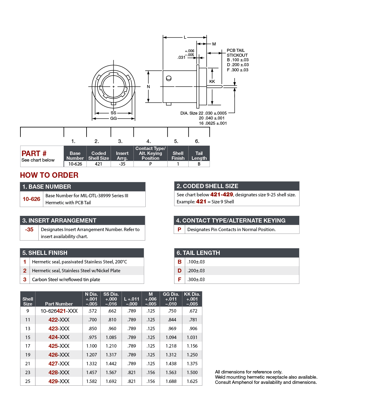
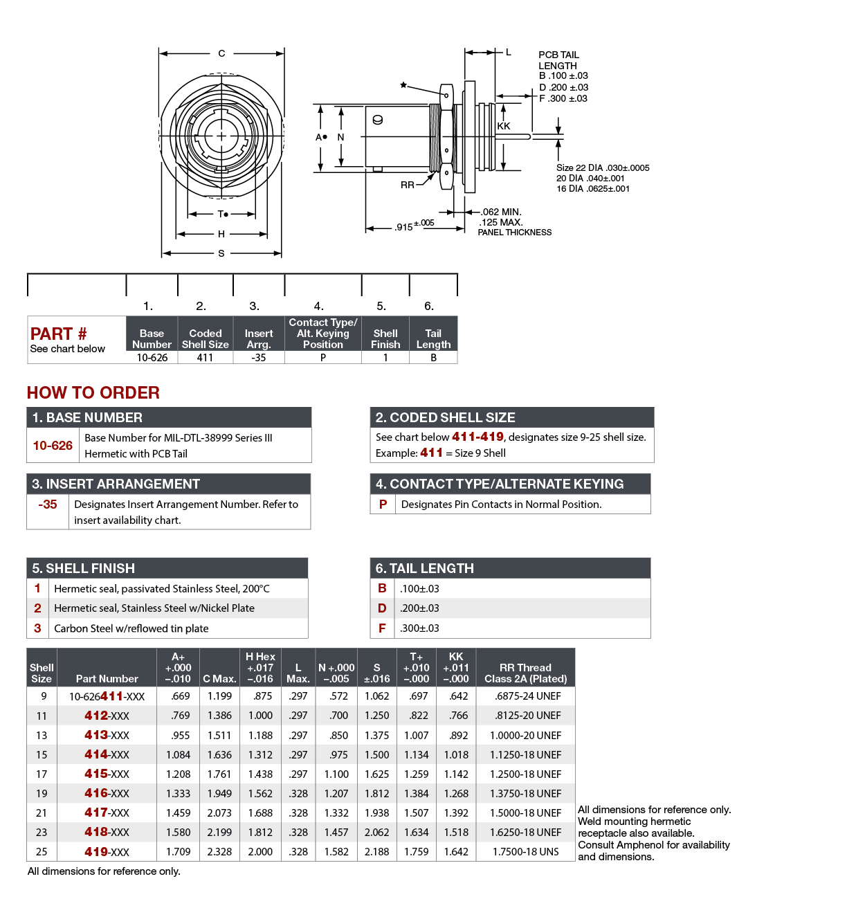
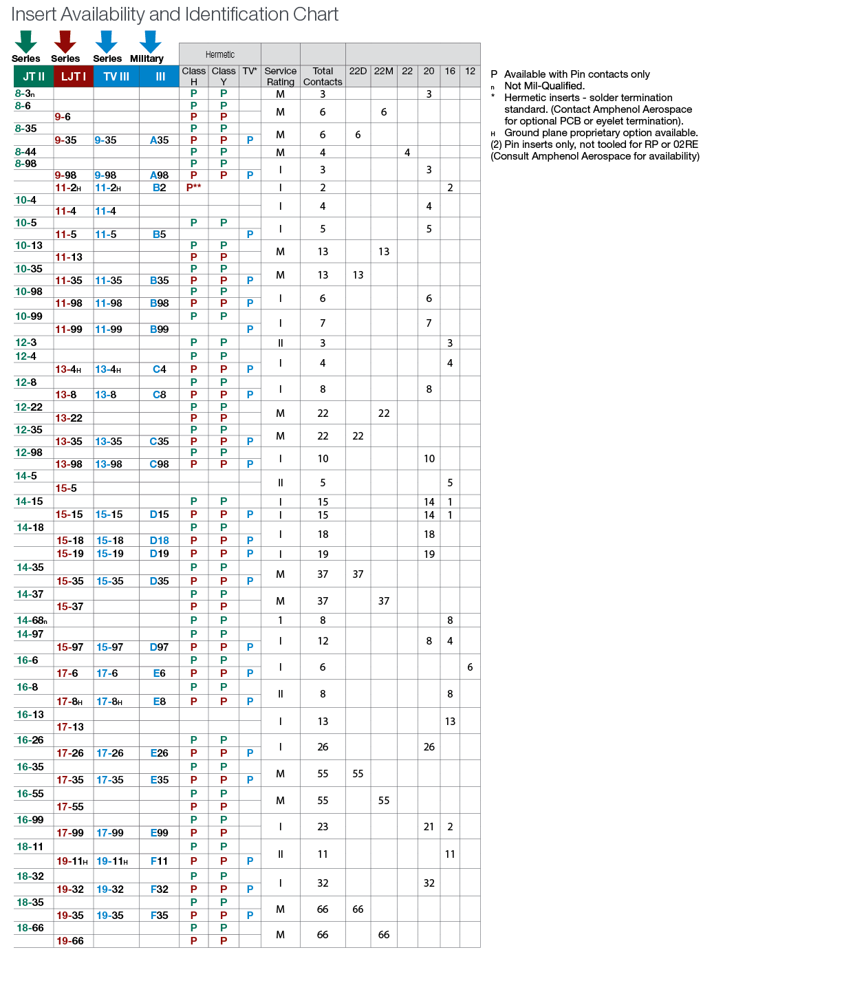
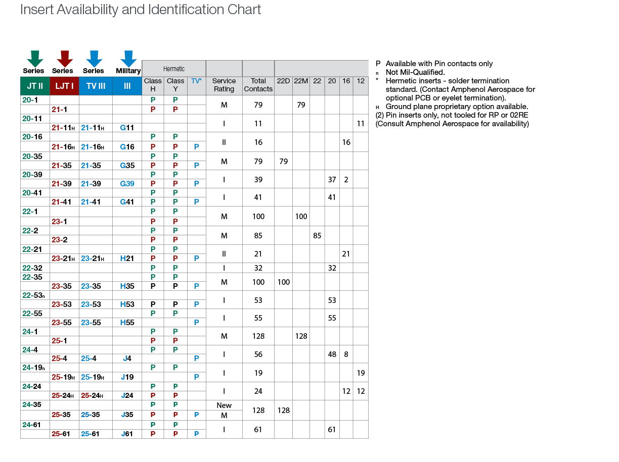
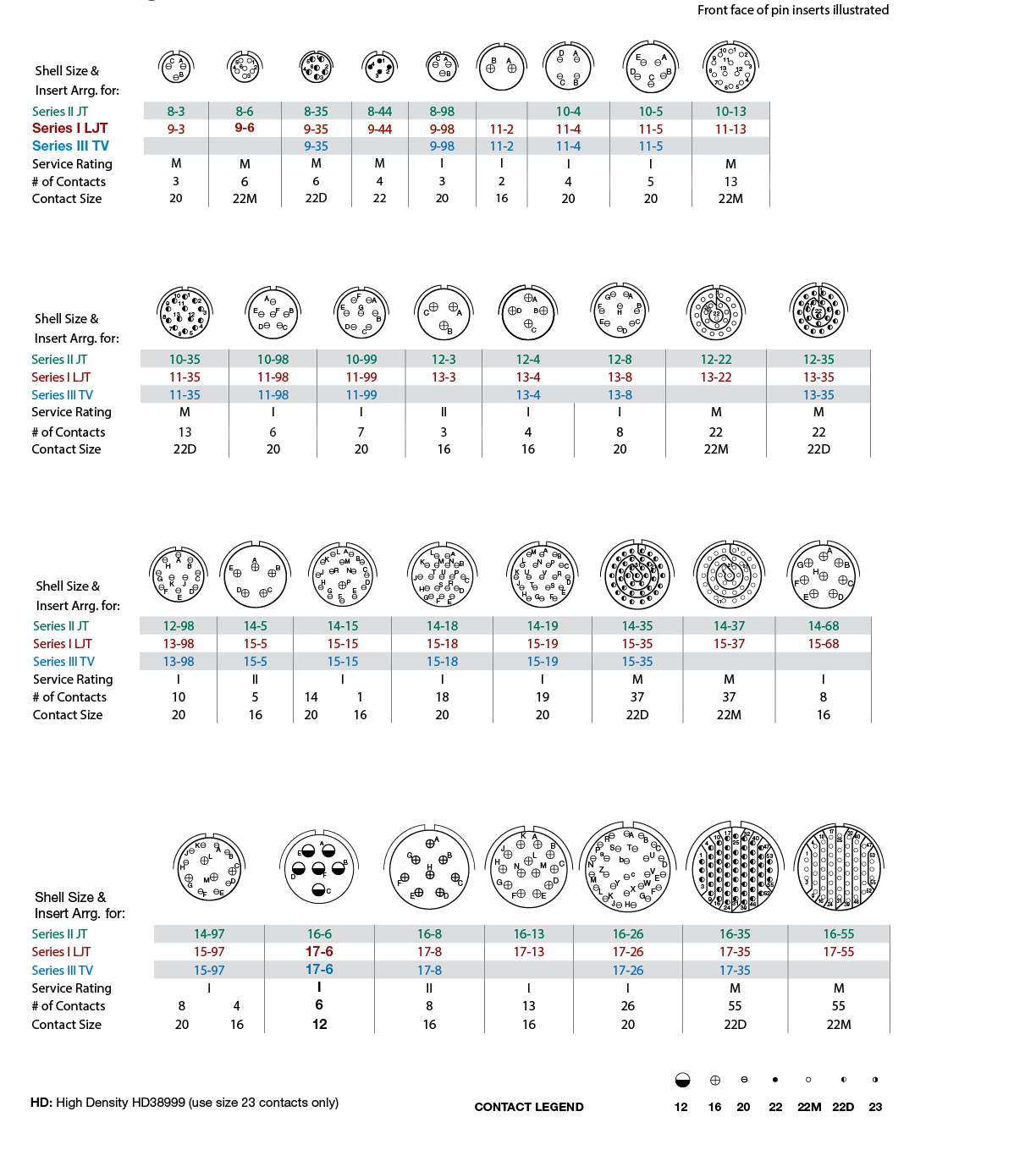
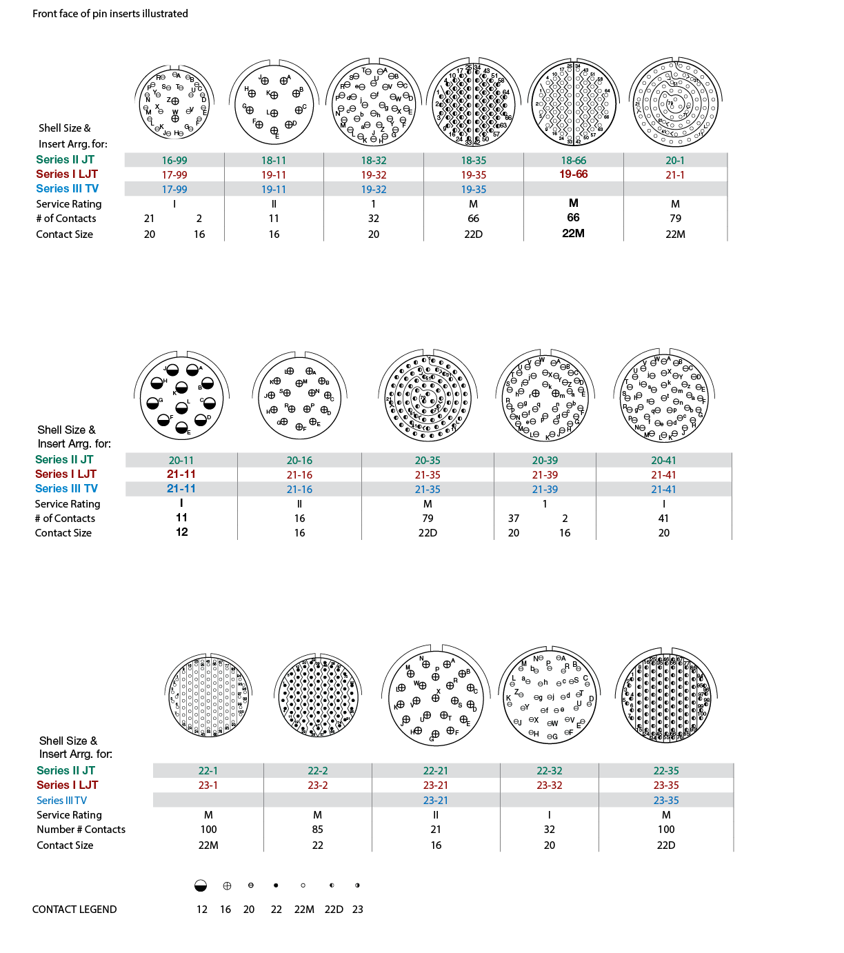
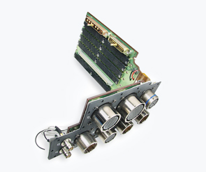
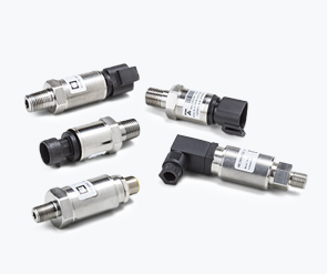
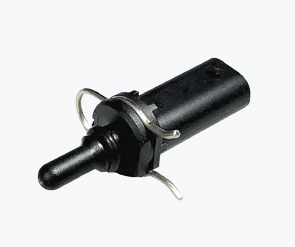
D38999 Series I - LJT Hermetic Connectors
Contact:
Description:
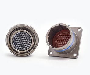
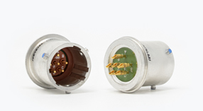
Amphenol MIL-DTL-38999 Series I Hermetic Connectors offer the highest performance capabilities for both general duty and severe environment applications meeting or exceeding MIL-DTL-38999 Series I requirements. Series 1 offers a three-point bayonet coupling system that allows for fast, 1/3 turn connector mating with the added benefit of a scoop-proof design, which eliminates mis-mating.
Amphenol commits to providing highly reliable and versatile MIL-DTL-38999 Series I connectors. Originally designed for the harshest of environments and most demanding of applications, Amphenol MIL-DTL-38999 Series I, Tri-Start connectors continue to evolve in pace with the needs of an ever-changing market.
Features & Benefits:
- Lightweight, Space-Saving Design
- Contact Protection 100% scoop-proof LJT design prevents bent pins and short circuits during mating
- Quick Positive Coupling 3 point bayonet lock system
- Mismating Eliminated With 5 key/keyway design
- Error Proof Alternate Positioning insured by different key/ keyway locations
- Fixed Solder Contacts Amphenol MIL-DTL-38999 Series I LJT are available in solder versions as both Commercial and Military qualified to MIL-DTL-27599
- Hermetic Air leakage limited to 1 X 10⁻⁷ cm3 per second
- Inventory Support Commonality Uses standard MIL-DTL-38999 contacts, insert arrangements and application tools.
- RoHS Compliant Product Available Consult Amphenol Aerospace Operations.
- How many Contacts?
Consider including a number of redundant contacts to accommodate any system developments you have planned for the future, or to comply with specified growth provisions. - What are the electrical requirements?
Work out a steady state and peak requirement for both the current and voltage. - Will your Glass-to-Metal Sealing be under any pressure?
Depending on the medium (for example, oil, water, or a vacuum) there may be a pressure differential to consider. Glass-to-Metal Sealing (GTMS) can be supplied in multi-pin preforms or, for high pressure applications in individual glass beads. - How will your GTMS be attached?
Will it be secured with a standard O-ring, for example, or welded in place? - What are your cable interface requirements?
Be sure to include any instructions for screen termination, potting requirements, and/or cable strain relief. - Do you require custom functionality?
If you have any specific requirements, such as electromagnetic compatibility (EMC) filters or printed circuit board (PCB) mounting, make sure they are included in your design specification. - What are your plating requirements?
We offer a wide range of in-house plating options, including tin, nickel, and hard and soft gold. We can also customize the plating to meet any special requirements. Note that gold-plated solder contacts should either be desoldered before installation or appropriate plating thickness specified, to avoid solder embrittlement. - Are there any environmental factors?
If your application will be operating in a harsh or hostile environment (exposed to shock, vibration, thermal changes or extreme temperatures, for example) these will need to be factored into the design. - What are the qualification requirements?
If qualification tests are required, these should be discussed and specified during the design phase. We are able to perform most qualification tests on the appropriate levels of assembly. - What testing will you need?
Examples include leak testing, pressure testing, and geometrical and electrical testing; including breakdown, voltage, and insulation resistance of finished parts. - Cabling and wiring too?
If you would like to extend your brief to include your cabling and wiring requirements, we can address those as well.
SERVICE RATING*
| Service Rating | Suggested Operating Voltage (Sea Level) |
Test Voltage | ||||
| AC (RMS) | DC | Sea Level | 50,000 ft. | 70,000 ft. | 110,000 ft. | |
| M | 400 | 500 | 1300 VRMS | 550 VRMS | 350 VRMS | 200 VRMS |
| N | 300 | 450 | 1000 VRMS | 400 VRMS | 260 VRMS | 200 VRMS |
| I | 600 | 850 | 1800 VRMS | 600 VRMS | 400 VRMS | 200 VRMS |
| II | 900 | 1250 | 2300 VRMS | 800 VRMS | 500 VRMS | 200 VRMS |
** Please note that the establishment of electrical safety factors is left entirely in the designer’s hands since they are in the best position to know
what peak voltage, switching surges, transients, etc. can be expected in a particular circuit.
| Hermetic Shell Components | ||
| Material/Finish | Service Class | |
| Military | Commercial | |
| Stainless Steel | Y | Y |
| Stainless Steel with Nickel Plate | N | YN |
| Hermetic Connectors | ||||
| Finish | Suffix | Indicated Finish Standard for JT Types Listed Below | Indicated Finish Standard for LJT Types Listed Below | |
| Military | Commercial | |||
| Carbon Steel Shell Tin Plated Shell and Contacts |
JT( )H / JT( )Y JTL( )H / JTL( )Y |
LJT( )Y LJT( )H |
||
| Carbon Steel Shell Tin Plated Shell and Gold Plated Contacts | MS (D) | |||
| Stainless Steel Shell Gold Plated Contacts | MS (E) | (162) | JTS( )Y JTLS( )Y |
LJTS( )Y |
