What is a Connector?
A connector is a device that joins two parts of an electrical circuit or different circuits together to form a larger circuit. Think of connectors as the links that allow different parts of an electrical system to communicate and work together.
Connectors are essential in a variety of applications because they connect the underlying system architecture in critical systems, providing power, functionality, and data and signal communication. They come in male (plug) and female (jack) forms.
Key Components:
- Plugs (Male-ended): These have protruding pins.
- Jacks (Female-ended): These have holes that receive the pins from the plugs.
Uses of Connectors:
- Connecting Cables to Systems: For example, plugging a power cable into a socket or an interface.
- Connecting Cables within a Circuit: Such as connecting the wires inside a computer to different components.
Why Use Ruggedized Connectors?
Ruggedized connectors are optimized for the harsh environments encountered by mission-critical systems:
- Reliability and Durability: Ruggedized connectors are built to withstand extreme environmental conditions, such as high temperatures, vibrations, and moisture, ensuring reliable performance in critical applications.
- Signal Integrity: They maintain signal integrity by minimizing signal loss and interference, which is crucial for maintaining accurate and uninterrupted communication in military and aerospace systems.
- Modularity and Scalability: Many ruggedized connectors are built in-alignment with open standards, enabling modular system designs and making it easier to upgrade or replace individual components without needing to redesign the entire system.
- Ease of Maintenance and Repair: The ability to quickly disconnect and reconnect parts enables easier maintenance, troubleshooting, and repairs, reducing downtime and improving overall system efficiency.
- Standardization and Compatibility: Many connectors adhere to industry standards, ensuring compatibility and interoperability between different systems and components.
- Enhanced Safety: High-quality connectors provide secure connections that reduce the risk of electrical hazards, such as short circuits and fires. They often include features like locking mechanisms and shielding for added safety.
What is a Cylindrical Connector?
A cylindrical connector is an electrical connector characterized by its round, robust housing designed for easy alignment and secure connections. Constructed from high-grade materials such as aluminum, stainless steel, or composite materials, cylindrical connectors often feature multiple contact points arranged in a circular pattern. They come in various types, including bayonet, threaded, and push-pull locking mechanisms, each offering quick and reliable connections. Their design includes sealing features to protect against environmental ingress.
Common Applications
- Aerospace and Defense
- Industrial Machinery
- Medical Devices
- Automobiles
SECTION I
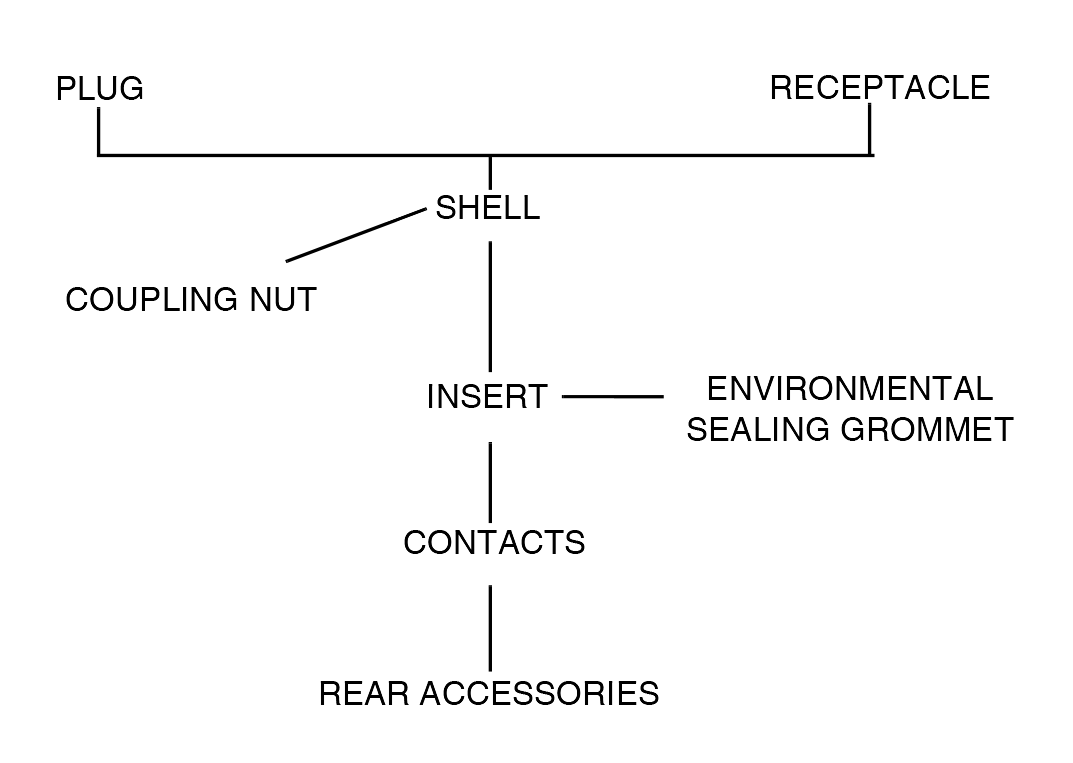
Nomenclature: Cylindrical Connectors
Basic Components- Shell (Houses Inserts & Contacts)
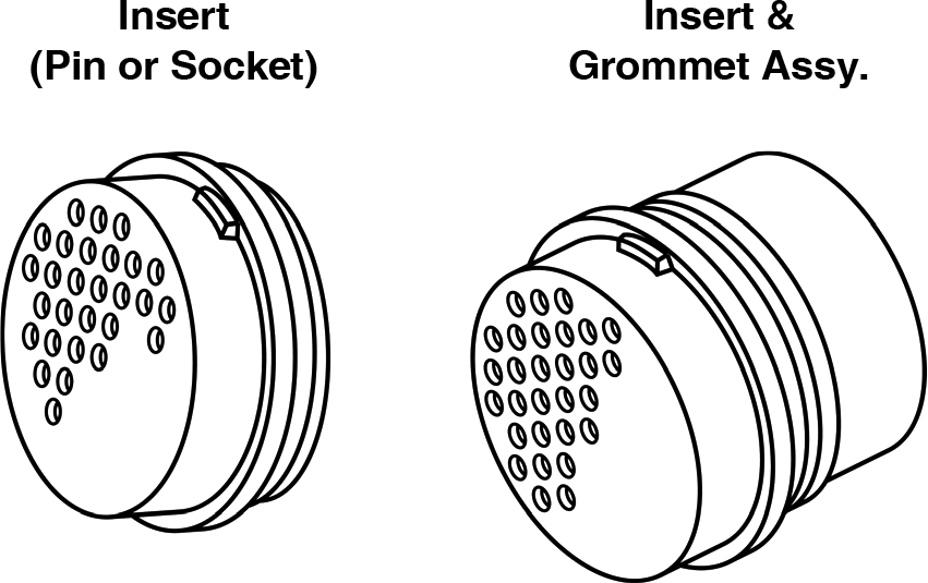
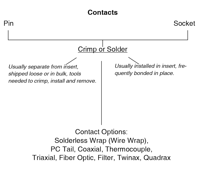
- Insert (Dielectric Contact Insulator) Pin or Socket
- Contact (Wire End Termination) (Electrical Engagement)
- Coupling Nut
- Accessories (Wire Seals, Cable Seals, Wire Support, etc.)

This connector style is sometimes referred to as a cable connecting “plug.” It does, however, mate with either a straight or 90 degree plug.
Nomenclature: Cylindrical Connectors and Contacts
Coupling Threaded, Bayonet
Shell Sizes (Typical MIL-DTL-5015) 8S, 10S, 10SL, 12S, 12, 14S, 14, 16S, 16, 18 20, 22, 24, 28, 32, 36, 40, 44, 48
"S" designates short shell and short contacts
Shell size denotes mating thread diameter in 16ths of an inch. For example, a size 8 shell denotes 8/16 of an inch with a 5000-28 UNEF thread.
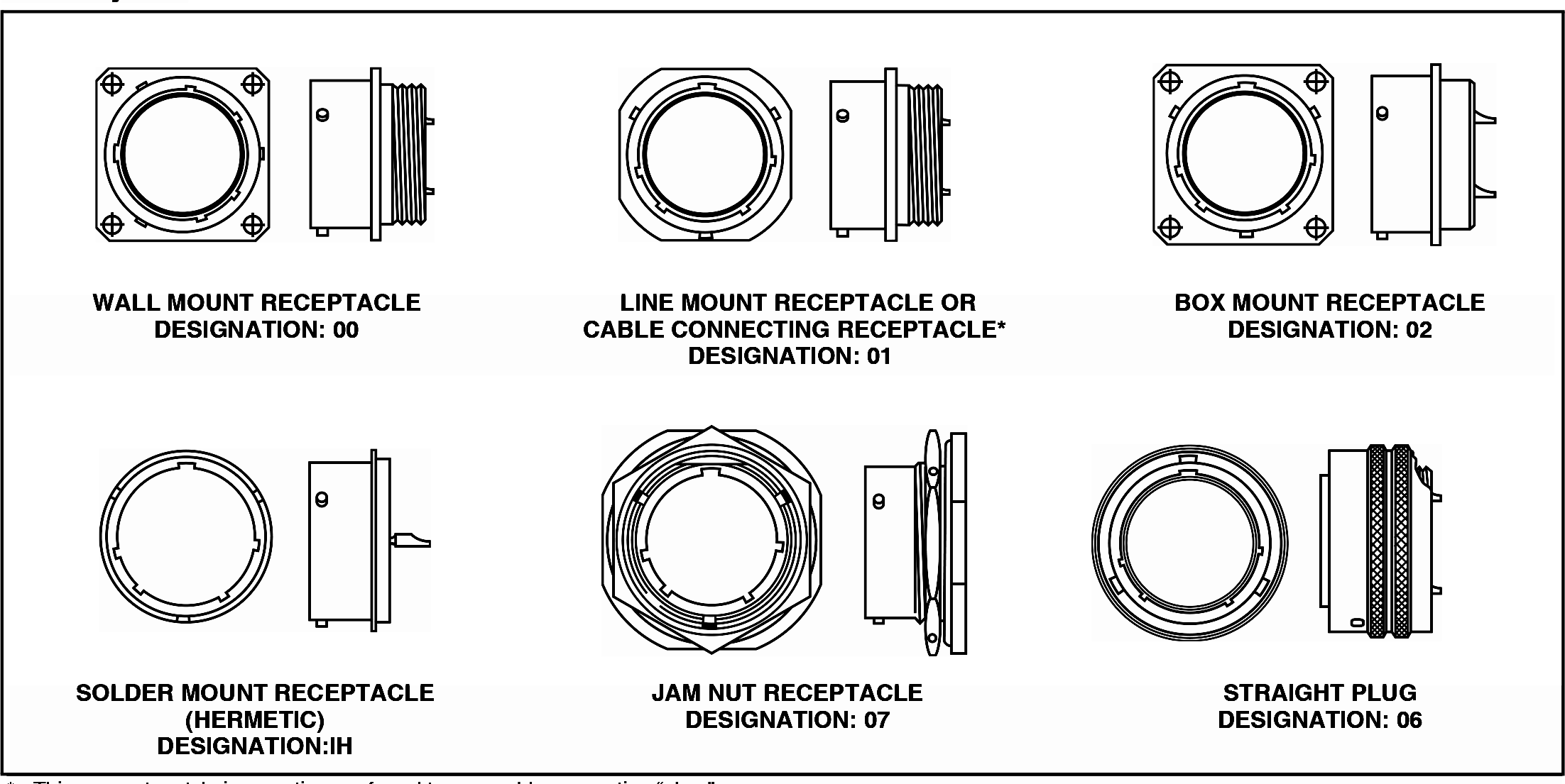
Style Designation |
|
|---|---|
| PLUG | SHELL STYLES |
| 06 | Straight |
| 08 | Angle |
| 09 | Flange Mount Receptacle |
| 05 | Straight, Less Rear Accessory |
| RECEPTACLE | SHELL STYLES |
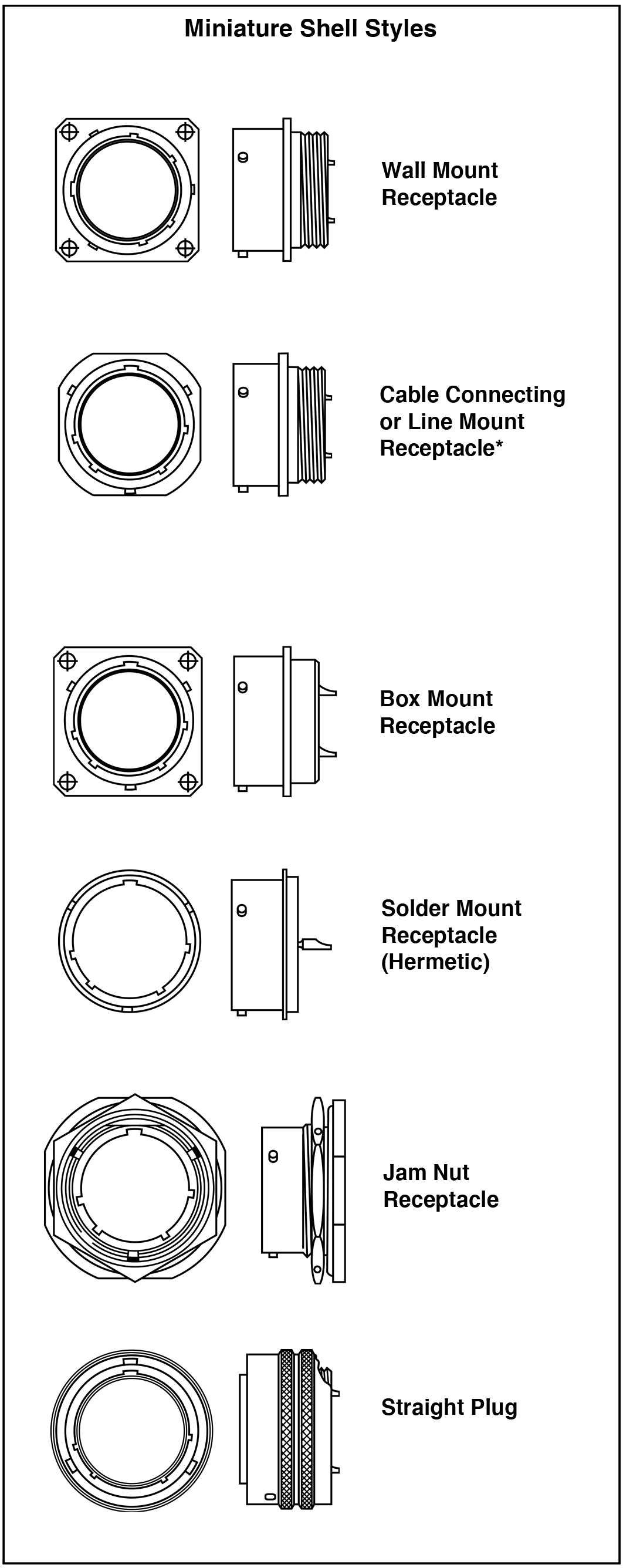
| 00 | 00 Wall Mount |
| 01 | 01 Cable Connecting or Line Mount Receptacle |
| 02 | Box Mount |
| 03 | Wall Mount, Less Rear Accessory |
| 04 | Line Mount, Less Rear Accessory |
| 07 | Jam Nut |
| IH | Solder Mount Hermetic |
- Solder
- Crimp
- Metal Clip Retention
- Dielectric Retention
May include a soft front interfacial seal (Bonded) if dielectric is hard, and a rear sealing grommet separate or attached.
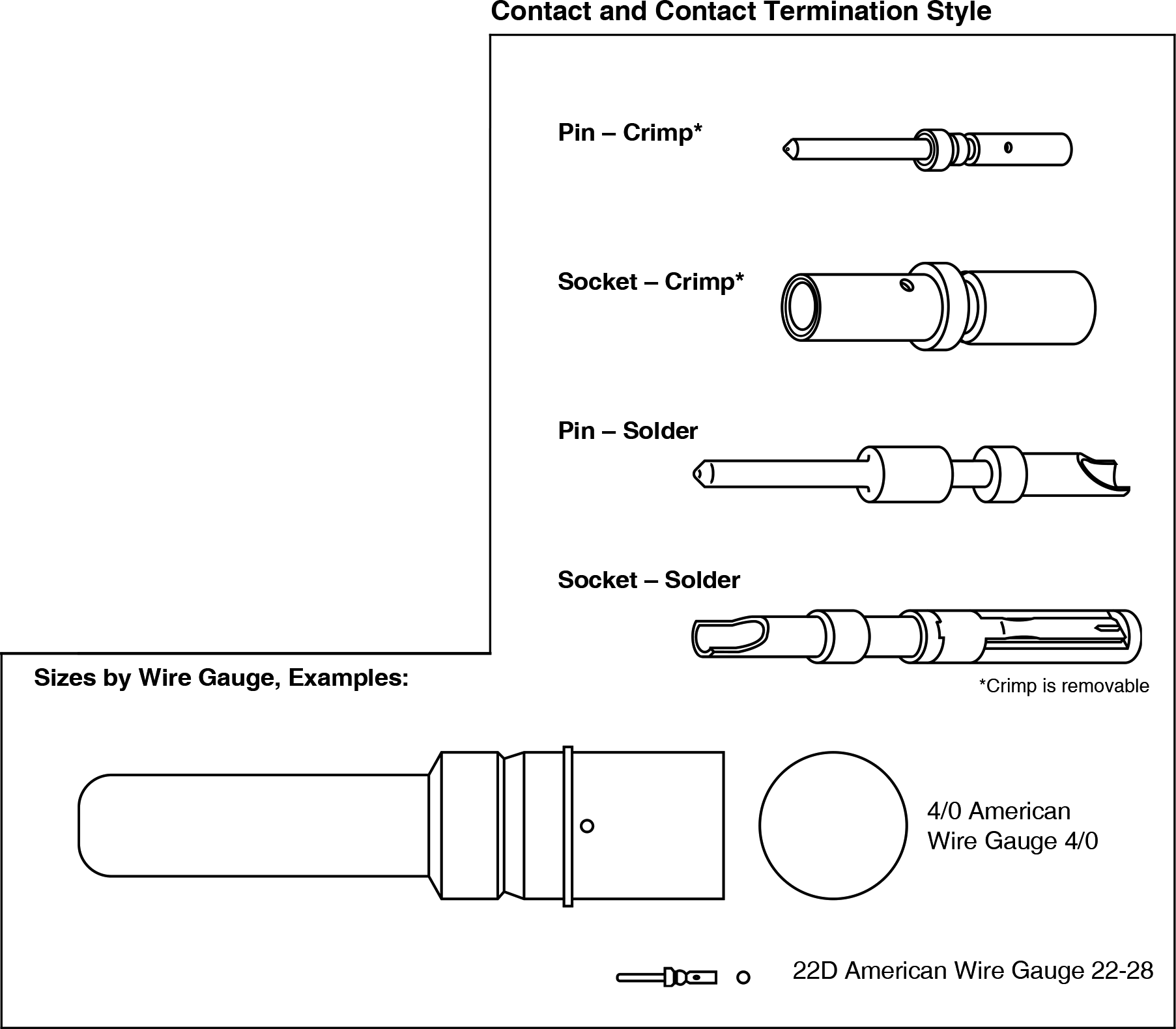
Contact and Contact Termination Style
Nomenclature: Cylindrical Connectors and Contacts, cont.
Contact Sizes
| Contact Size | 22D | 22M | 22 | 20 | 16 |
|---|---|---|---|---|---|
| American Wire Gauge Wire Size (AWG) | 22-28 | 24-28 | 22-26 | 20-24 | 16-20 |
| Contact Size | 12 | 8 | 4 | 0 |
|---|---|---|---|---|
| American Wire Gauge Wire Size (AWG) | 12-14 | 8-10 | 4-6 | 0-2 |
Accessories
- Adapters – straight, 90°, 75° – conduit, environmental, open wire bundle, EMI, etc.
- Compression ring – wire seal
- Clamp – cable sealing
- Stain relief – clamp, kellems grip
- Potting boot – straight, angle, universal
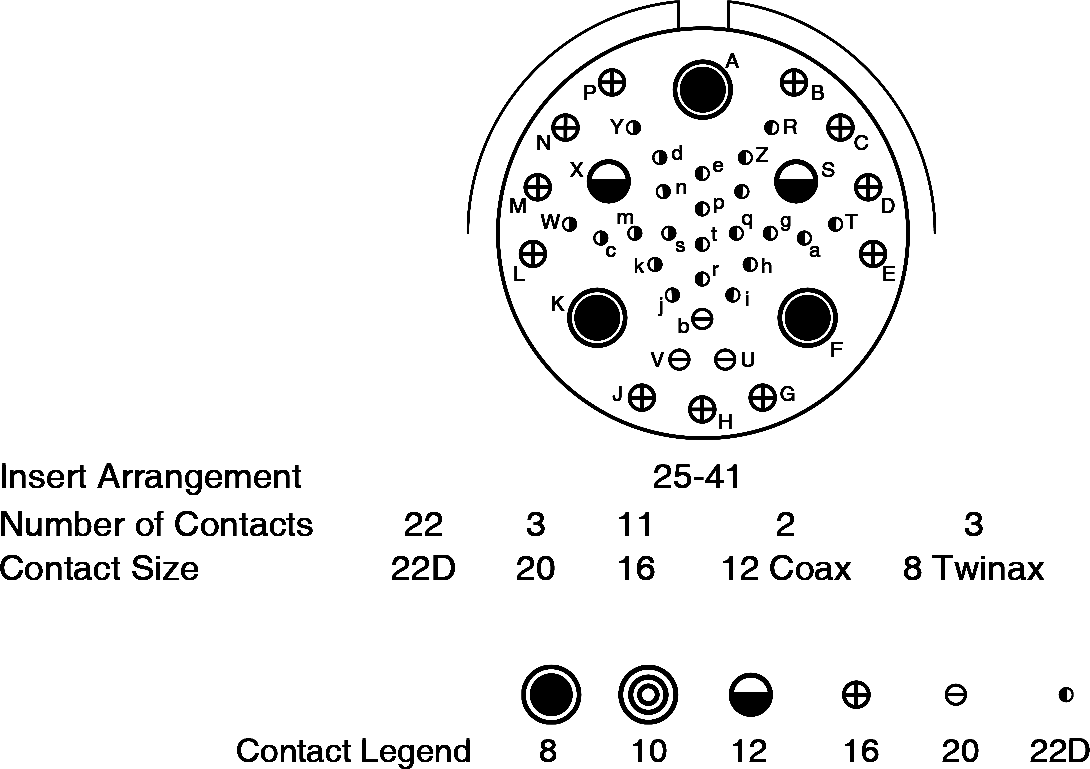
MIL-DTL-38999 connectors allow users to mix a variety of different power, signal, shielded, fiber optic and high speed contact styles within a common insert.
The insert arrangement below is an arrangement for Tri-Start MIL-DTL-38999 Series III connectors. It shows the variety of contacts that can be designed into a shell size 25. Typically, customers specify the contacts sizes and power they require and chose an existing arrangement that fits their needs. For special new configurations, engineering will design the arrangement of contacts to fit within material and performance criteria.
Contacts and Fiber Optic Termini for Cylindrical Connectors
Amphenol’s broad contact product range for Cylindrical Connectors includes:
- Standard 500 cycle and 1500 cycle, M39029 type power and signal contacts
- Crimp contacts for front or rear release connector applications
- Solder type, fixed contacts with cup or eyelet termination
- Thermocouple contacts
- RADSOK® sockets for high amperage power contacts
- Spring-loaded and push-pull types
- Filter contacts: Pi type tubular or Pi type planar for MF, HF, VHF, and UHF frequencies
- High frequency shielded coax, triax and twinax contacts
- High speed differential twinax and quadrax contacts
- For cylindrical connector attachment to Printed Circuit Boards:
- PC tail contacts for signal and power applications, in coax, twinax, triax, differential twinax and quadrax designs
- Compliant pin (Press fit) contacts
- Fiber optic Termini: MIL-T-29504 type or MT ferrules or ARINC801 termini
SECTION II
Major MIL-Specifications by Type
- Standard, MIL-DTL-5015
- Amphenol 97 Series
- Heavy Duty, MIL-DTL-22992
- Proprietary Variations
- Older larger series of connectors
- Found on many pieces of military equipment and commercial applications
- Mostly heavy current carrying connectors
- Early types had only solder type contacts
- Later revision to MIL Spec also added crimp type contacts
- Amphenol supplies both the solder and crimp types to the MIL Spec
- Amphenol supplies both solder and crimp versions under proprietary part numbers
- Several variations of basic MIL-DTL-5015 and MIL-DTL-22992 types are available in the same and additional contact arrangements, such as the QWL, QWLD, 10-214000 Series, 10-244000 Series and others.
- See Amphenol catalog sections:
- MIL-DTL-5015 Cylindrical 12-020,
- MIL-DTL-5015 Modifications 12-021,
- Heavy Duty Cylindrical 12-052,
- Commercial Aircraft Cylindrical 12-101,
- 97 Series (MIL-DTL-5015 Proprietary) 12-022,
- GT Series Bayonet 12-024.
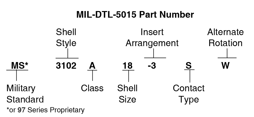
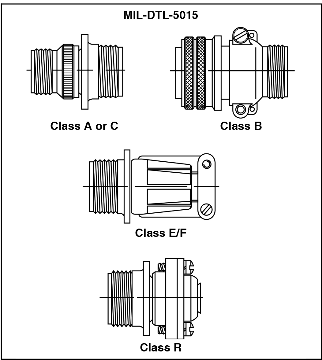
- Basic part number for MIL-DTL-5015 Series as supplied by Amphenol is MS310X A, C, E, F or R
- MIL-DTL-5015 threaded coupling - 1 key/keyway shell polarization
MIL-DTL-5015 Shell Styles |
|
|---|---|
| 3100 | Wall Mount Receptacle |
| 3101 | Cable Connecting Receptacle* |
| 3102 | Box Mount Receptacle |
| 3106 | Straight Plug |
| 3108 | 90° Plug |
| 3107 | Quick Disconnect Plug (97 Series only) |
Contact Sizes
| Contact Size | 16 | 12 | 8 | 4 | 0 |
|---|---|---|---|---|---|
| American Wire Gauge Wire Size (AWG)** | 16-20 | 12-14 | 8-10 | 4-6 | 0-2 |
This connector style is sometimes referred to as a cable connecting “plug.” It does, however, mate with either a straight or 90 degree plug.
** Crimp adapter for small gauge wire is available, part number 10-074696-XXX.
Mating Halves
- Plugs: MS3106, MS3107, MS3108 or 97-3106, 97-3107, 97-3108
- Receptacles: MS3100, MS3102, MS3101, 97-3101, 97-3100, 97-3102
Other Non-MIL-Mates, Flange Mounted
- Flange Mounted Plug: FP3106, 97-5105
- Thru-bulkhead Receptacle: TBF
See also 10-74XXX and 10-873XX in catalog section MIL-DTL-5015 Mods. for jam nut receptacles (Non-MIL)
Alternate Positions of Insert Arrangements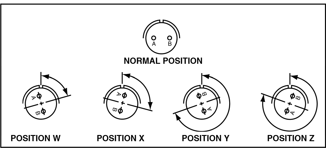
Heavy Duty Cylindrical Connectors
- Class L - for the heaviest loads
– Current range 40 to 200 amperes
– Direct current or single/three phase, 60/400 Hertz alternating current
– Automatic grounding for safety
- QWLD - for most power and control circuits
– Military qualified connectors and commercial equivalents available
– Increased shell size for greater durability than similar standard connectors
- Class L and QWLD have 5 key/keyway shell polarization and double stub thread coupling
- QWL – a more economical, compact heavy duty design for commercial power and control applications; single key shell polarization and double stub thread coupling
MIL-DTL-22992 Series Connectors
Classes C, R and L Part Number BreakdownThe ordering procedure for QWLD MS-Approved Connectors is illustrated by part number MS17343R20N27PW as shown below:
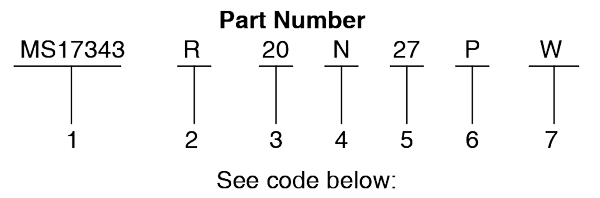
- MS Numbers
- MS17343 - designates wall mount receptacle
- MS17344 - designates straight plug
- MS17345 - designates cable connecting receptacle
- MS17346 - designates box mount receptacle
- MS17347 - designates jam nut receptacle with rear accessory threads (wall mount)
- MS17348 - designates jam nut receptacle (box mount)
- Class C designates pressurized; used where circuit integrity is protected by a pressure differential R designates environmental; (see Heavy Duty Cylindrical catalog 12-052 for definition)
- Shell Size Available in shell sizes 12 through 44. See catalog 12-052 for dimensional data
- Shell Finish C for conductive or N for non-conductive
- Insert Arrangement Current MS insert arrangements are listed in catalog 12-052, Heavy Duty Cylindrical
- Contact Type “P” designates pin contacts; “S” for socket contacts
7. Alternate Insert Rotations:
Used to prevent cross-mating of connectors. Absence of a letter in this space indicates normal (0°) position of the insert. See catalog for alternate insert rotation illustrations.
See catalog 12-052 for proprietary equivalents such as 10- 194XXX Series. Also see catalog 12-053 for QWL Series.
The ordering procedure for Class “L” Connectors is illustrated by part number MS90555C32412SY as shown below:
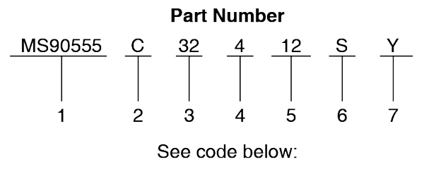
- MS Numbers
- MS90555 - designates wall mount receptacle (power source)
- MS90556 - designates straight plug
- MS90557 - designates cable connecting receptacle without coupling ring
- MS90558 - designates wall mount plug with coupling ring (equipment end)
- Shell Finish
C (conductive) for AC or N (non-conductive) for DC circuits
- Shell Size
Relates directly to current carrying capability
- Size 28 – 40 amperes
- Size 32 – 60 amperes
- Size 44 – 100 amperes
- Size 52 – 200 amperes
- Main shell Key/keyway Position
N designates normal position. Three other positions (4, 5 and 6) of the main shell key/keyway prevent cross-mating or incompatible voltages. Refer to the individual connector style descriptions in catalog 12-052 for applicability.
- Insert Arrangement
Determined by connector size (current carrying capability) and cable configuration to be accommodated. See catalog for insert arrangement pattern illustrations.
- Contact Type
“P” designates pin contacts. “S” for socket contacts. MS90555 and MS90557 are supplied with socket contacts only. MS90556 and MS90558 are supplied with pin contacts only.
- Alternate Insert Rotation
Used to prevent cross-mating of incompatible frequencies. Absence of a letter in this space indicates normal (0°) position of the insert. See catalog for individual insert arrangement description.
SECTION III
Major MIL-Specifications by Type Miniature, MIL-DTL-26482
Miniature PT-Types MIL-DTL-26482
- Widely used smaller connectors
- Extensive use on military equipment including aircraft as well as commercial applications
- Available with either crimp or solder type contacts
- 3 point bayonet coupling
- Popular low cost series
- 5 Key/keyway shell polarization
- Amphenol supplies MIL-Spec types as well as proprietary versions
- MS311X or PT, solder type contacts (Series 1)
- MS312X or PT-SE, crimp type contacts (front release) (Series 1)
- MS347X or MB1, crimp type contacts (rear release) (Series 2)
- Modifications of Basic Series are:
- PT-CE, crimp type contacts (front release) no MIL P/N, intermates with MS connectors
- PC, double stub threaded coupling, bright cadmium plated, - (available with either crimp or solder contacts) no MIL P/N, does not intermate with PT types
- SP, same as PT except wider flanges for back panel mounting, anodic coating, no MIL P/N, intermates with MS connectors
- DC, same as PT except resistant to aircraft fluids, no MIL P/N, intermates with MS connectors
- Other modifications and specials available
- For details on above series see Amphenol catalog sections:
- “Miniature Cylindrical” 12-070
- “Commercial Aircraft Cylindricals” 12-101.
MIL-DTL-26482 Series 2 is the same as MIL-DTL-83723 Series1 and will intermate with all PT connectors. The Series features rear removable contacts – accessories are ordered separately. MIL-DTL-83723 Series 1 has been superseded by MIL-DTL-26482 Series 2.


How to Order BY MILITARY PART NUMBER
MIL-DTL-26482 Series 2 Connectors

Connector Type
MS designates Military Standard
2. Connector Style
3470 - wall mounting receptacle with narrow flange
3472 - wall mounting receptacle with wide flange
3471 - cable connecting receptacle
3474 - jam nut receptacle 3476 - straight plug
3475 - straight plug with RFI grounding fingers
3. Service Class
L - aluminum shell, electroless nickel finish, fluid resistant insert
A - aluminum shell, black anodized finish, non-conductive fluid resistant insert
W - aluminum shell, olive drab cadmium plated, fluid resistant insert
Note: For stainless steel shell, passivated, order by Amphenol®/Matrix® proprietary Class G.
Class L inactivates older classes E and R (Ref. MIL-C-26482)
4., 5. Shell size and insert arrangement - See chart on page 9 and pattern drawings that follow.
6. Contact Types
P - designates pin
S - designates socket
A - designates less pins
B - designates less sockets
Note: Use A & B only when other than a full complement of power contacts is to be installed.
7. Insert Rotation
“W”, “X”, “Y”, “Z” designate that insert is rotated in its shell from normal position. No letter required for normal (no rotation) position.
How to Order BY PROPRIETARY PART NUMBER
MIL-DTL-26482 Series 2 Connectors

1. Connector Type
MB1 designates Amphenol®/Matrix® Bayonet Coupling Connector
2. Connector Style
0 - wall mounting receptacle with narrow flange
1 - wall mounting receptacle with wide flange
3 - cable connecting receptacle
4 - jam nut receptacle
6 - straight plug
8 - straight plug with RFI grounding fingers
3. Service Class
A - aluminum shell, black anodize finish, non-conductive, fluid resistant insert
R - aluminum shell, electroless nickel finish, fluid resistant insert
G - stainless steel shell, passivated, fluid resistant insert
W - aluminum shell, cadmium plated, olive drab finish, fluid resistant insert
4., 5. Shell size and insert arrangement - See chart on page 9 and pattern drawings that follow.
6. Contact Types
P designates pin
S designates socket
7. Insert Rotation
“W”, “X”, “Y”, “Z” designate that insert is rotated in its shell from normal position. No letter required for normal (no rotation) position.
8. Modification Number
Consult Amphenol, Sidney, NY for information.
For strain reliefs use the following modification codes:
(189) E-nut M85049/31 configuration
(190) Straight strain relief M85049/52 configuration
(191) 90° strain relief M85049/51 configuration
For ordering information on accessories, such as protection caps and backshell hardware, contact Amphenol, Sidney, NY.
Miniature Crimp Connectors
Part Number Breakdown
Proprietary Part Number Construction for Miniature Crimp Connectors
To more easily illustrate ordering procedures, part number PT00SE-20-41PW (SR) is shown as follows:

- Connector Family
- PT designates standard olive drab cadmium plated Tri-Lock coupling connector
- SP designates connector similar to PT except for anodic coating and larger flange and mounting holes for back panel mounting of receptacles
- Shell Style
- “00” designates wall mount receptacle
- “01” designates cable connecting receptacle
- “02” designates box mount receptacle
- “06” designates straight plug
- “07” designates jam nut receptacle
- “08” designates 90° plug
- Service Class
- “SE” designates crimp, environmental (MIL-DTL-26482)
- “SP” designates crimp, potted type (MIL-DTL-26482)
Both of the above are Amphenol proprietary versions of the MIL-DTL-26482 Series 1 crimp contact connector and offer 15 lbs. contact retention for size 20 contacts, 25 lbs. for size 16 contacts.
- “CE” designates crimp, environmental
- “CP” designates crimp, potted type
Both of the above are original Amphenol crimp connectors and offer 7 lbs. contact retention for size 20 contacts, 9 lbs. for size 16 contacts.
- “20” designates shell size. Shell sizes available are 8 through 24.
- “20-41” designates insert arrangement
- “P” designates pin contacts; “S” for socket contacts
- “W” designates that insert is rotated in its shell from the standard position to alternate position W. The basic rotations are W, X, Y, and Z. No letter required for normal (no rotation) position.
- “SR” designates a strain relief clamp. Deviation suffixes would be inserted here. For example, (005) would indicate the metal parts (except contacts) would have anodic coating.
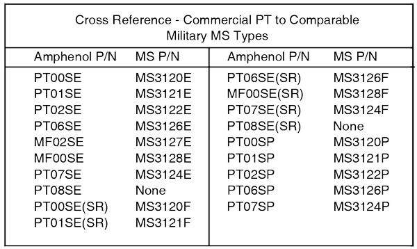
Part Number Nomenclatures for MS/PT Crimp Connectors to MIL-DTL-26482 Specification
To more easily illustrate ordering procedures, part number MS3120E-20-41PW is broken down as follows:
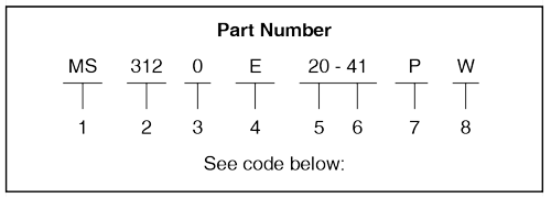
- “MS” designates Military Standard
- “312” designates basic family number for MIL-Spec 26482 crimp type
- Shell Style
“0” designates wall mount receptacle
“1” designates cable connecting receptacle
“2” designates box mount receptacle
“4” designates jam nut receptacle
“6” designates straight plug
“7” designates box mount receptacle with dual mounting holes
“8” designates wall mount receptacle with dual mounting holes - Service Class
“E” designates environmental resisting connector
“F” designates environmental resisting connector with strain relief
“P” designates potted type with potting boot - “20” designates shell size. Shell sizes available are 8 through 24.
- “20-41” designates insert arrangement
- “P” designates pin contacts; “S” for socket contacts
- “W” designates that the insert is rotated in its shell from the standard position to alternate position W. The basic rotations are W, X, Y, and Z. No letter required for normal (no rotation) position.
Miniature Solder Connectors
Part Number Breakdown
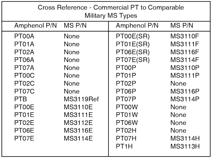
Part Number Nomenclature for Miniature Solder Connectors
To more easily illustrate ordering procedures, part number PT00A-20-41PW (SR) is shown as follows:

- Connector Family
- PT - designates standard olive drab cadmium plated Tri-Lock coupling connector. This is the Amphenol® proprietary version of the MIL-DTL-26482 solder contact connector.
- PC - designates a bright cadmium plated connector with double stub thread coupling
- SP - designates connector similar to PT except for anodic coating and larger flange and mounting holes for back panel mounting
- Shell Style
- “00” designates wall mount receptacle
- “01” designates cable connecting receptacle
- “02” designates box mount receptacle
- “06” designates straight plug
- “07” designates jam nut receptacle
- PTB designates thru-bulkhead receptacle
- PTI designates solder mount receptacle
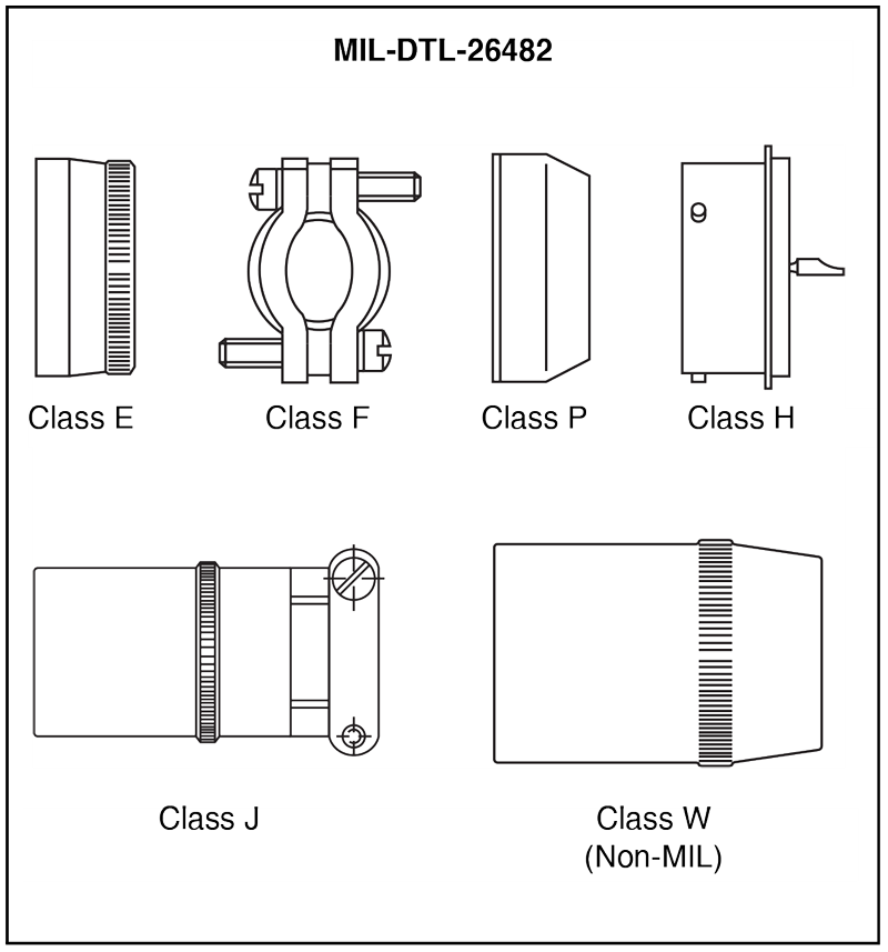
- Service Class
- “A” designates general duty backshell
- “C” designates pressurized receptacle
- “E” designates environmental resisting with grommet and clamping nut
- “J” designates clamp assembly for moisture proofing multijacketed cables, with strain relief
- “P” designates potted with potting boot
- “W” designates clamp assembly for moisture-proofing, multijacketed cables
- “H” designates hermetic seal receptacle
- “20” designates shell size. Shell sizes available are 6 through 24.
- “20-41” designates insert arrangement
- “P” designates pin contacts; “S” for socket contacts
- “W” designates that insert is rotated in its shell from the standard position to alternate position W. The basic rotations are W, X, Y, and Z. No letter required for normal (no rotation) position.
- “SR” designates a strain relief clamp. Deviation suffixes would be inserted here. For example, (005) would indicate the metal parts (except contacts) would have alumilite plating.
Part Number Nomenclatures for MS/PT Solder Connectors to MIL-DTL-26482 Specification
To more easily illustrate ordering procedures, part number MS3110E20-41PW is shown as follows:
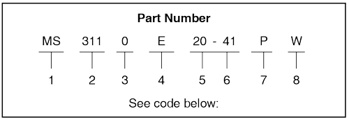
- “MS” designates Military Standard
- “311” designates basic family number for MIL-Spec 26482 solder type
- Shell Style
“0” designates wall mount receptacle
“1” designates cable connecting receptacle
“2” designates box mount receptacle
“4” designates jam nut receptacle
“6” designates straight plug - Service Class
“E” designates environmental resisting connector with grommet and clamping nut
“F” designates environmental resisting connector with grommet and strain relief
“J” designates clamp assembly for moisture proofing multijacketed cables, with strain relief
“P” designates potted type with potting boot - “20” designates shell size. Shell sizes available are 8 through 24.
- “20-41” designates insert arrangement
- “P” designates pin contacts; “S” for socket contacts
- “W” designates that the insert is rotated in its shell from the standard position to alternate position W. The basic rotations are W, X, Y, and Z. No letter required for normal (no rotation) position.
This connector style is sometimes referred to as a cable connecting “plug.” It does, however, mate with either a straight or 90 degree plug.
Also see PTB - Thru- bulkhead, double-ended receptacle in Miniature Cylindrical catalog.
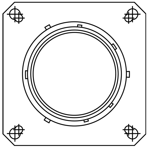
Wide Flange - Back Panel Mount:
MS3127 Box Mount, MS3128 Wall Mount
Shell Sizes
6, 8, 10, 12, 14, 16, 18, 20, 22, 24
| Contact Size | 20 | 16 | 12 |
|---|---|---|---|
| American Wire Gauge Wire Size (AWG) | 20-24 | 16-20 | 12-14 |