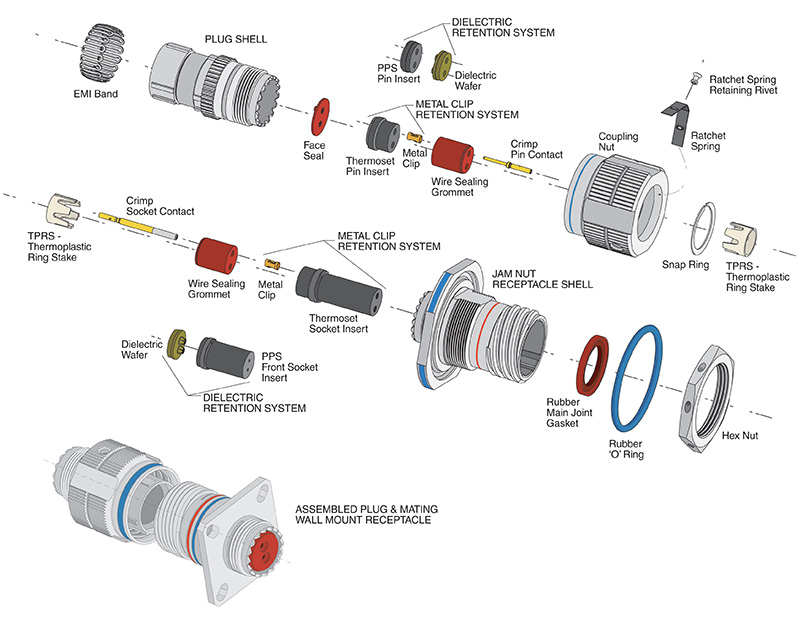
SECTION IV
Major MIL-Specifications by Type
- Subminiature, MIL-DTL-38999*
- MIL-DTL-27599
- Preferred for new design by the Military
- Greatest growth potential of all cylindricals
- “State of the Art” technology and performance
- MIL-DTL-27599 has molded-in solder type contacts
- MIL-DTL-38999 has rear release, crimp removable contacts
- SJT has features of both the JT and LJT and is a NATO preferred connector in Europe
- MIL-DTL-38999 Series I, II & III will not intermate
- MIL-DTL-27599 Series I & II will not intermate
- MIL-DTL-38999 and MIL-DTL-27599, Series I and II will intermate respectively
- For more information, see Amphenol’s combined circular product catalog, 12-C3. This new catalog contains sections for:
- MIL-DTL-38999, Series I and II (formerly was in individual catalog 12-090)
- MIL-DTL-27599, Series I and II (formerly was in product data sheet PDS-158)
- MIL-DTL-38999, Series III (formerly was in individual catalog 12-092)
- SJT proprietary MIL-DTL-38999 type (formerly was in individual catalog 12-091)
- High Frequency contacts for circular connectors (formerly was in individual catalog 12-130)
MIL-DTL-27599
Series I (LJT-Solder)
- 100% scoop-proof
- Molded-in solder type contacts
- Options include PCB, wire wrap contacts
- High contact density (up to 128 contacts)
- Shell grounding fingers standard on all plugs
- Intermateable with MIL-DTL-38999 Series I
- Bayonet coupling
- 5 key/keyway polarization with 4 alternate keyings
Series II (JT-Solder)
- Low profile, light-weight, non-scoop-proof
- Molded-in solder type contacts
- Options include PCB, wire wrap contacts
- High contact density (up to 128 contacts)
- Shell grounding fingers available as option on plug
- Intermateable with MIL-DTL-38999 Series II
- Bayonet coupling
- 5 key/keyway polarization with 4 alternate keyings
Series I (LJT-R)
- 100% scoop-proof
- High density arrangements (up to 128 contacts)
- Contact sizes 12 through 22D plus size 16, 12, 8 coax, and size 8 twinax
- Bayonet coupling
- DOD preferred
- Corrosion resistant (500 hr. salt spray) finish available
- Removable crimp, PCB, wire wrap, twinax, and coax contacts available
- Options include Hermetics, Filters and Thermocouples
- 5 key/keyway polarization with 4 alternate keyings
- Shell grounding fingers are standard on all plug
- Triple-web grommet seal
- Available in a Fail Safe Lanyard Release plug: see Amphenol catalog 12-C3.
Series II (JT-R)
- High density arrangements (up to 128 contacts)
- Low silhouette, light-weight non-scoop-proof
- Bayonet coupling
- Contact sizes 12 through 22D plus size 16 & 12 coax
- 5 key/keyway polarization with 4 alternate keyings
- Removable crimp, PCB, wire wrap and coax contacts available
- Corrosion resistant (500 hr. salt spray) finish available
- Options include Hermetics, Filters and Thermocouples
- Shell grounding fingers on plugs are an option
- Triple-web grommet seal
- Available in Fail Safe Lanyard Release plug
* Catalog 12-C3 catalog was released Jan. 2010. It covers the majority of the circular connector products offered by Amphenol Aerospace. Go online for this catalog at www.amphenol-aerospace.com, where the product sections can be viewed and downloaded. The next version of this combined circular product catalog (12-C4) will be available within 2011. Consult Amphenol Aerospace, Sidney NY for more information
Subminiature JT/LJT
Part Number Breakdown
PROPRIETARY PART NUMBER
To more easily illustrate ordering procedure, part number JT00RE-22-2PA( ) is shown as follows:

See code below
1. Connector Type:
JT designates standard Junior Tri-Lock connector
LJT designates long Junior Tri-Lock connector
LJTS JTS designates high temperature connector
LJTN JTN designates chemical and fuel resistant
JTL designates miniature mounting dimensions
JTLN designates miniature mounting dimensions chemical resistant
JTLS designates miniature mounting dimensions high temperature
LJTPQ JTPQ designates back panel mounted wall mounting receptacle LJTP JTP designates back panel mounted box mounting receptacle
LJTPN JTPN designates back panel mounted chemical resistant
LJTPS JTPS designates back panel mounted high temperature
JTG* designates plug with grounding fingers
JTNG* designates plug with grounding fingers chemical resistant
*Grounding fingers standard on all LJT plugs.
2. Shell Style
“00” designates wall mount receptacle
“01” designates line mount receptacle
“02” designates box mount receptacle
“06” designates straight plug
“07” designates jam nut receptacle
“08” designates 90-degree plug
“I” designates solder mount receptacle – hermetic
3. Service Class: Solder contacts/connectors
“P” for potting applications – These connectors are supplied with a potting boot. All shells are designed with integral features to retain potting boots
“A” for general duty applications (JT series only)
“A (SR)” – threaded rear design with strain relief
“C” for pressurized applications
“C” (SR)” – threaded rear design with strain relief
“H” for hermetic applications – Fused compression glass sealed inserts. Leakage rate less than .01 micron cu. ft/hr. (1 x 10⁻⁷ cc/sec.) at 15 psi differential.
“Y” same as “H” with interfacial seal
“T” for MS27599A applications – General duty – pressurized (receptacles only) (LJT series only)
3. Service Class: Crimp contacts/connectors
“RP” for potting crimp applications – Supplied with spacer grommet and potting boot.
“RE” for environmental crimp applications – Supplied with a grommet and compression nut (JT Series only). Can be supplied with strain relief integral with compression nut “RE (SR).”
“RT” for environmental applications – Supplied without rear accessories. Design provides serrations on rear threads of shells. For additional information defining complete description of service class, consult Amphenol, Sidney, NY.
4. Shell Size
JT shell sizes available from 8 through 24. LJT shell sizes available from 9 through 25.
5. Insert Arrangement:
22-2 designates insert arrangement. Refer to catalog 12-C1 for additional insert patterns.
6. Contact Style
“P” designates pin contacts; “S” designates socket contacts.
7. Alternating Keying
“A” designates alternate keying connector assembly. Other basic alternate keys are “B”, “C” and “D”. No letter required for normal (no rotation) position.
8. “SR” designates a strain relief clamp. Strain reliefs are available only on “A”, “C” and “RE” class connectors.
9. Finish variation suffix.
Not applicable to box mounting style.
| Finish | Military Finish Data | Finish Suffix | Finish plus “SR” Suffix |
|---|---|---|---|
| Cadmium plated nickel base | A | (SR) | |
| Olive drab cadmium plate nickel base | B | (014) | (386) |
| Electroless nickel | F | (023) | (424) |
| Anodic coating (Alumilite) | C | (005) | (300) |
| Chromate treated (Iridite 14-2) | (011) | (344) |
MILITARY TYPES
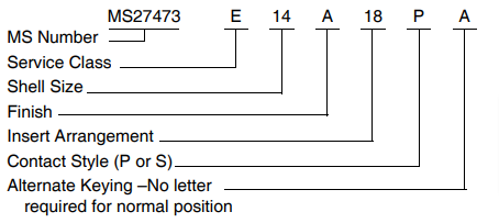
Military Service Class
E Environmental, same as RE
T Environmental, same as RT
Y Hermetically sealed, same as Y
P Potting, same as RP
For finish variations see finish data on following page.
For MS depictions and dimensional data see applicable MILSpec. (MIL-DTL-38999, MIL-DTL-27599).
Amphenol Gage Code 77820
Subminiature JT/LJT
Specifications
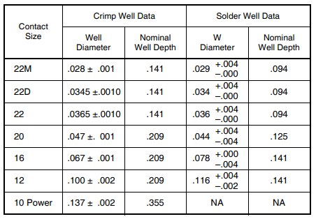
CONTACT RATING
| Contact Size | Test Current | Maximum Millivolt Drop Crimp* | Maximum Millivolt Drop | ||
|---|---|---|---|---|---|
| Solder & Crimp | Hermetic | Solder | Hermetic | ||
| 22M | 3 | 2 | 45 | 20 | 60 |
| 22D | 5 | 3 | 73 | 85 | |
| 22 | 5 | 3 | 73 | 20 | 85 |
| 20 | 7.5 | 5 | 55 | 20 | 60 |
| 16 | 13 | 10 | 49 | 20 | 85 |
| 12 | 23 | 17 | 42 | 20 | 85 |
| 10 Power | 33 | NA | 33 | NA | NA |
* When tested using silver plated wire
Service Rating
| Service Rating | Suggested Operating Voltage (Sea Level) | Test Voltage(Sea Level) | Test Voltage 50,000 Ft. | Test Voltage 70,000 Ft. | Test Voltage 110,000 Ft. | |
|---|---|---|---|---|---|---|
| AC (RMS) | DC | |||||
| M | 400 | 500 | 1300 VRMS | 550 VRMS | 350 VRMS | 200 VRMS |
| N | 300 | 450 | 1000 VRMS | 400 VRMS | 260 VRMS | 200 VRMS |
| I | 600 | 850 | 1800 VRMS | 600 VRMS | 400 VRMS | 200 VRMS |
| II | 900 | 1250 | 2300 VRMS | 800 VRMS | 500 VRMS | 200 VRMS |
** Please note that the establishment of electrical safety factors is left entirely in the designer’s hands, since he is in the best position to know what peak voltages, switching surges, transients, etc. can be expected in a particular circuit.
FINISH DATA
| Aluminum Shell Components Non-Hermetic | ||||
|---|---|---|---|---|
| Finish | Suffix | Indicated Finish Standard for JT Types Listed Below | Standard for LJT Types Listed Below | |
| Military | Proprietary | |||
| Cadmium Plated Nickel Base | MS (A) | - | JT/JTG/JTL/JTP | LJT/LJTP |
| Anodic Coating (Alumilite) | MS (C) | (005) | JTS/JTPS/JTLS | LJTPS/LJTS |
| Chromate Treated (Iridite 14-2) | (011) | JTN/JTPN/JTLN | LJTN/LJTPN | |
| Olive Drab Cadmium Plate Nickel Base | MS (B) | (014) | ||
| Electroless Nickel | MS (F) | (023) | ||
| Hermetic Connectors | ||||
|---|---|---|---|---|
| Material Finish | Suffix | Indicated Finish Standard for JT Types Listed Below | Indicated Finish Standard for JT Types Listed Below | |
| Military | Proprietary | |||
| Carbon Steel Shell Tin Plated Shell and Contacts | JT ( ) H/JT ( ) Y JTL ( ) H/JTL ( ) Y |
LJT ( ) Y/LJT ( ) H | ||
| Carbon Steel Shell Tin Plated Shell and Gold Plated Contacts | MS (D) | (452) special termination (468) solder cup | ||
| Stainless Steel Shell Gold Plated Contacts | MS (E) | (162) | JTS ( ) Y JTLS ( ) Y |
LJTS ( ) Y |
MIL-DTL-38999 LJT-R/JT-R and Accessories
Cross Reference List
| Series or Accessory | MS Part No. | Amphenol Part No. | Description |
|---|---|---|---|
| Ac | MS27502AXXA | 10-275197-XX7 | Cap, Recept. Series I No Chain |
| Ac | MS27502BXXA | 10-275197-XX9 | |
| Ac | MS27502FXXA | 10-275197-XXG | |
| Ac | MS27501AXXA | 10-275196-XX7 | Cap, Plug Series I, No Chain |
| Ac | MS27501BXXA | 10-275196-XX9 | |
| Ac | MS27501FXXA | 10-275196-XXG | |
| Ac | MS27342AXX-1 | 10-440390-XX7 (Series II) | Adapter |
| Ac | MS27342BXX-1 | 10-440390-XX9 (Series II) | |
| Ac | MS27342CXX-1 | 10-440390-XX5 (Series II) | |
| Ac | MS27342FXX-1 | 10-440390-XXG (Series II) | |
| Ac | MS27342AXX-2 | 10-241055 Series II | |
| Ac | MS27342BXX-2 | 10-457452 Series I | |
| Ac | MS27342CXX-2 | ||
| Ac | MS27342FXX-2 | ||
| Ac | MS27510AXXA | 10-241853-XX7 | Cap, Plug Series II, No Chain |
| Ac | MS27510BXXA | 10-241853-XX9 | |
| Ac | MS27510CXXA | 10-241853-XX5 | |
| Ac | MS27510FXXA | 10-241853-XXG | |
| Ac | MS27511AXXA | 10-241856-XX7 | Cap, Recept. Series II, No Chain |
| Ac | MS27511BXXA | 10-241856-XX9 | |
| Ac | MS27511CXXA | 10-241856-XX5 | |
| Ac | MS27511FXXA | 10-241856-XXG | |
| I | MS27466EXXAXXP/S | LJT00RE-XX-XXP/S | Wall Mount Receptacle |
| I | MS27466EXXBXXP/S | LJT00RE-XX-XXP/S (014) | |
| I | MS27466EXXFXXP/S | LJT00RE-XX-XXP/S (023) | |
| I | MS27466TXXAXXP/S | LJT00RE-XX-XXP/S (014) | |
| I | MS27466TXXBXXP/S | LJT00RT-XX-XXP/S (014) | |
| I | MS27466TXXFXXP/S | LJT00RT-XX-XXP/S (023) | |
| I | MS27466PXXAXXP/S | LJT00RP-XX-XXP/S | |
| I | MS27466PXXBXXP/S | LJT00RP-XX-XXP/S (014) | |
| I | MS27466PXXFXXP/S | LJT00RP-XX-XXP/S (023) | |
| I | MS27467EXXAXXP/S | LJT06RE-XX-XXP/S | Straight Plug |
| I | MS27467EXXBXXP/S | LJT06RE-XX-XXP/S (014) | |
| I | MS27467EXXFXXP/S | LJT06RE-XX-XXP/S (023) | |
| I | MS27467TXXAXXP/S | LJT06RT-XX-XXP/S | |
| I | MS27467TXXBXXP/S | LJT06RT-XX-XXP/S (014) | |
| I | MS27467TXXFXXP/S | LJT06RT-XX-XXP/S (023) | |
| I | MS27467PXXAXXP/S | LJT06RP-XX-XXP/S | Straight Plug |
| I | MS27467PXXBXXP/S | LJT06RP-XX-XXP/S (014) | |
| I | MS27467PXXFXXP/S | LJT06RP-XX-XXP/S (023) | |
| I | MS27468EXXAXXP/S | LJT07RE-XX-XXP/S | Jam Nut Mount Receptacle |
| I | MS27468EXXBXXP/S | LJT07RE-XX-XXP/S (014) | |
| I | MS27468EXXFXXP/S | LJT07RE-XX-XXP/S (023) | |
| I | MS27468TXXAXXP/S | LJT07RT-XX-XXP/S | |
| I | MS27468TXXBXXP/S | LJT07RT-XX-XXP/S (014) | |
| I | MS27468TXXFXXP/S | LJT07RT-XX-XXP/S (023) | |
| I | MS27468PXXAXXP/S | LJT07RP-XX-XXP/S | |
| I | MS27468PXXBXXP/S | LJT07RP-XX-XXP/S (014) | |
| I | MS27468PXXFXXP/S | LJT07RP-XX-XXP/S (023) | |
| I | MS27469YXXDXXP | LJT00Y-XX-XXP | Wall Mount Recept.,Hermetic Seal |
| I | MS27469YXXEXXP | LJTS00Y-XX-XXP | |
| I | MS27470YXXDXXP | LJT07Y-XX-XXP | Jam Nut Mount Recept., Hermetic Seal |
| I | MS27470YXXEXXP | LJTS07Y-XX-XXP | |
| I | MS27471YXXDXXP | LJTIY-XX-XXP | Solder Mount Recept., Hermetic Seal |
| I | MS27471YXXEXXP | LJTSIY-XX-XXP |
| Series or Accessory | MS Part No. | Amphenol Part No. | Description |
|---|---|---|---|
| II | MS27472EXXAXXP/S | JT00R-EXX-XXP/S | Wall Mount Receptacle, Hermetic Seal |
| II | MS27472EXXBXXP/S | JT00RE-XX-XXP/S (014) | |
| II | MS27472EXXCXXP/S | JTS00R-EXX-XXP/S | |
| II | MS27472EXXFXXP/S | JT00RE-XX-XXP/S (023) | |
| II | MS27472TXXAXXP/S | JT00RT-XX-XXP/S | |
| II | MS27472TXXBXXP/S | JT00RT-XX-XXP/S (014) | |
| II | MS27472TXXCXXP/S | JTS00RT-XX-XXP/S | |
| II | MS27472TXXFXXP/S | JT00RT-XX-XXP/S (023) | |
| II | MS27472PXXAXXP/S | JT00RP-XX-XXP/S | |
| II | MS27472PXXBXXP/S | JT00RP-XX-XXP/S (014) | |
| II | MS27472PXXCXXP/S | JTS00RP-XX-XXP/S | |
| II | MS27472PXXFXXP/S | JT00RP-XX-XXP/S (023) | |
| II | MS27473EXXAXXP/S | JT06RE-XX-XXP/S | Straight Plug |
| II | MS27473EXXBXXP/S | JT06RE-XX-XXP/S (014) | |
| II | MS27473EXXCXXP/S | JT06RE-XX-XXP/S | |
| II | MS27473EXXFXXP/S | JT06RE-XX-XXP/S (023) | |
| II | MS27473TXXAXXP/S | JT06RT-XX-XXP/S | |
| II | MS27473TXXBXXP/S | JT06RT-XX-XXP/S (014) | |
| II | MS27473TXXCXXP/S | JT06RT-XX-XXP/S | |
| II | MS27473TXXFXXP/S | JT06RT-XX-XXP/S (023) | |
| II | MS27473PXXAXXP/S | JT06RP-XX-XXP/S | |
| II | MS27473PXXBXXP/S | JT06RP-XX-XXP/S (014) | |
| II | MS27473PXXCXXP/S | JTS06RP-XX-XXP/S | |
| II | MS27473PXXFXXP/S | JT06RP-XX-XXP/S (023) | |
| II | MS27474EXXAXXP/S | JT07RE-XX-XXP/S | Jam Nut Mount Receptacle |
| II | MS27474EXXBXXP/S | JT07RE-XX-XXP/S (014) | |
| II | MS27474EXXCXXP/S | JTS07RE-XX-XXP/S | |
| II | MS27474EXXFXXP/S | JT07RE-XX-XXP/S (023) | |
| II | MS27474TXXAXXP/S | JT07RT-XX-XXP/S | |
| II | MS27474TXXBXXP/S | JT07RT-XX-XXP/S (014) | |
| II | MS27474TXXCXXP/S | JTS07RT-XX-XXP/S | |
| II | MS27474TXXFXXP/S | JT07RT-XX-XXP/S (023) | |
| II | MS27474PXXAXXP/S | JT07RP-XX-XXP/S | |
| II | MS27474PXXBXXP/S | JT07RP-XX-XXP/S (014) | |
| II | MS27474PXXCXXP/S | JTS07RP-XX-XXP/S | |
| II | MS27474PXXFXXP/S | JT07RP-XX-XXP/S (023) | |
| II | MS27475YXXDXXP | JT00Y-XX-XXP | Wall Mount Recept., Hermetic Seal |
| II | MS27475YXXEXXP | JTS00Y-XX-XXP | |
| II | MS27476YXXDXXP | JT02Y-XX-XXP | Box Mount Recept., Hermetic Seal |
| II | MS27476YXXEXXP | JTS0Y-XX-XXP | |
| II | MS27477YXXDXXP | JT07Y-XX-XXP | Jam Nut Mount Recept., Hermetic Seal |
| II | MS27477YXXEXXP | JTS07Y-XX-XXP | |
| II | MS27478YXXDXXP | JTIY-XX-XXP | Solder Mount Recept., Hermetic Seal |
| II | MS27478YXXEXXP | JTSIY-XX-XXP | |
| II | MS27479EXXCXXP/S | JTS00RE-XX-XXP/S | Wall Mount Recept., Inactive, Use MS27472 |
| II | MS27479TXXCXXP/S | JTS00RT-XX-XXP/S | |
| II | MS27480EXXCXXP/S | JTS06RE-XX-XXP/S | Straight Plug, Inactive, Use MS27473 |
| II | MS27480TXXCXXP/S | JTS06RT-XX-XXP/S | |
| II | MS27481EXXCXXP/S | JTS07RE-XX-XXP/S | Jam Nut Mount Recept., Inactive, Use MS27474 |
| II | MS27481TXXCXXP/S | JTS07RT-XX-XXP/S | |
| II | MS27482YXXEXXP | JTS00Y-XX-XXP | Wall Mount Recept., Hermetic Seal, Inactive, Use MS27475 |
| II | MS27483YXXEXXP | JTS07Y-XX-XXP | Jam Nut Mount Recept., Hermetic Seal, Inactive, Use MS27477 |
MIL-DTL-38999 LJT-R/JT-R and Accessories
Cross Reference List (Cont.)
| Series or Accessory | MS Part No. | Amphenol Part No. | Description |
|---|---|---|---|
| II | MS27484EXXAXXP/S | JTG06RE-XX-XXP/S | Straight Plug with Grounding Spring |
| II | MS27484EXXBXXP/S | JTG06RE-XX-XXP/S (014) | |
| II | MS27484EXXFXXP/S | JTG06RE-XX-XXP/S (023) | |
| II | MS27484TXXAXXP/S | JTG06RT-XX-XXP/S | |
| II | MS27484TXXBXXP/S | JTG06RT-XX-XXP/S (014) | |
| II | MS27484TXXFXXP/S | JTG06RT-XX-XXP/S (023) | |
| II | MS27484PXXAXXP/S | JTG06RP-XX-XXP/S | |
| II | MS27484PXXBXXP/S | JTG06RP-XX-XXP/S (014) | |
| II | MS27484PXXFXXP/S | JTG06RP-XX-XXP/S (023) | |
| Ac | MS27485AXX | 10-528399-XX7 | Ring Potting Boot Series II |
| Ac | MS27485BXX | 10-528399-XX9 | |
| Ac | MS27485CXX | 10-528399-XX5 | |
| Ac | MS27485FXX | 10-528399-XXG | |
| Ac | MS27486-XX-1 | 10-241912-XX | Potting Boot Straight Series II |
| Ac | MS27486-XX-2 | 10-241990-XX | Potting Boot 90 Degree Series II |
| Ac | MS27487-XX-1 | 10-450910-XX, Includes MS27489 | Kit EMR Adapter Straight Series I & II |
| Ac | MS27487-XX-2 | 10-450911-XX | Kit EMR Adapter 90 Degree Series I & II |
| Ac | MS27488-12-1 | 10-405996-121 | Plug Sealing Grommet |
| Ac | MS27488-16-1 | 10-405996-161 | |
| Ac | MS27488-20-1 | 10-405996-201 | |
| Ac | MS27488-22-1 | 10-405996-241 | |
| Ac | MS27489-XXX | 10-352425-XX | Adapter Reducer EMR for use with MS27487 |
| I | MS27490-XX | 10-407035-XX5 | Contact-Socket |
| II | MS27491-XX | 10-251416-XX5 | Contact-Socket |
| II | MS27492-XX | 10-251416-XXH | Contact-Socket Inactive, use MS27491 |
| II | MS27493-XX | 10-251415-XX5 | Contact-Pin |
| II | MS27494-XX | 10-251415-XXH | Contact-Pin Inactive, use MS27493 |
| I & II | MS27495R-XX | 11-8675-XX | Tool Contact Removable Metal |
| I & II | MS27495A-XX | 11-8674-XX | Tool Contact Assembly Metal |
| I | MS27496EXXAXXP/S | LJT02RE-XX-XXP/S | Box Mount Receptacle |
| I | MS27496EXXBXXP/S | LJT02RE-XX-XXP/S (014) | |
| I | MS27496EXXFXXP/S | LJT02RE-XX-XXP/S (023) | |
| II | MS27497EXXAXXP/S | JTPQ00RE-XX-XXP/S | Back Panel Wall Mount Receptacle. |
| II | MS27497EXXBXXP/S | JTPQ00RE-XX-XXP/S (014) | |
| II | MS27497EXXCXXP/S | JTPSQ00RE-XX-XXP/S | |
| II | MS27497EXXFXXP/S | JTPQ00RE-XX-XXP/S (023) | |
| II | MS27497TXXAXXP/S | JTPQ00RT-XX-XXP/S | |
| II | MS27497TXXBXXP/S | JTPQ00RT-XX-XXP/S (014) | |
| II | MS27497TXXCXXP/S | JTPSQ00RT-XX-XXP/S | |
| II | MS27497TXXFXXP/S | JTPQ00RT-XX-XXP/S (023) | |
| II | MS27497PXXAXXP/S | JTPQ002P-XX-XXP/S | |
| II | MS27497PXXBXXP/S | JTPQ002P-XX-XXP/S (014) | |
| II | MS27497PXXCXXP/S | JTPSQ002P-XX-XXP/S | |
| II | MS27497PXXFXXP/S | JTPQ00RP-XX-XXP/S (023) | |
| II | MS27497VXXAXXP/S | JTP00RE-XX-XXP/S | |
| II | MS27497VXXBXXP/S | JTP00RE-XX-XXP/S (014) | |
| II | MS27497VXXCXXP/S | JTPS00RE-XX-XXP/S | |
| II | MS27497VXXFXXP/S | JTP00RE-XX-XXP/S (023) |
| Series or Accessory | MS Part No. | Amphenol Part No. | Description |
|---|---|---|---|
| I | MS27498EXXAXXP/S | LJT08RE-XX-XXP/S | 90 Degree Plug Inactive for Design |
| I | MS27498EXXBXXP/S | LJT08RE-XX-XXP/S (014) | |
| II | MS27499EXXAXXP/S | JT02RE-XX-XXP/S | Box Mount Receptacle |
| II | MS27499EXXBXXP/S | JT02RE-XX-XXP/S (014) | |
| II | MS27499EXXCXXP/S | JTS02RE-XX-XXP/S | |
| II | MS27499EXXFXXP/S | JT02RE-XX-XXP/S (023) | |
| II | MS27500EXXAXXP/S | JT08RE-XX-XXP/S | 90 Degree Plug Inactive for Design |
| II | MS27500EXXBXXP/S | JT08RE-XX-XXP/S (014) | |
| I | MS27501AXXC | 10-421399-XX7 | Cover Plug with chain |
| I | MS27501BXXC | 10-421399-XX9 | |
| I | MS27501FXXC | 10-421399-XXG | |
| I | MS27502AXXC | 10-427406-XX7 | Cover Receptacle with chain |
| I | MS27502BXXC | 10-427406-XX9 | |
| I | MS27502FXXC | 10-427406-XXG | |
| II | MS27503YXXEXXP | JTSIY-XX-XXP | Solder Mount Receptacle, Hermetic Seal Inactive, use MS27503 |
| II | MS27504EXXCXXP/S | JTS00RE-XX-XXP/S | Box Mount Receptacle, Inactive, use MS27499 |
| I | MS27505EXXAXXP/S | LJTP02RE-XX-XXP/S (023) | Back Panel Wall Mount Receptacle |
| I | MS27505EXXBXXP/S | LJTP02RE-XX-XXP/S (014) | |
| I | MS27505EXXFXXP/S | LJTP02RE-XX-XXP/S (023) | |
| I | MS27506AXX-1 | 10-436792-XX7 | Adapter, Strain Relief, Clamp Bars |
| I | MS27506BXX-1 | 10-436792-XX9 | |
| I | MS27506FXX-1 | 10-436792-XXG | |
| II | MS27506AXX-2 | 10-433992-XX7 | |
| II | MS27506BXX-2 | 10-433992-XX9 | |
| II | MS27506CXX-2 | 10-433992-XX5 | |
| II | MS27506FXX-2 | 10-433992-XXG | |
| I & II | MS27507A-XX | 10-415693-XX7 | Adapter, 90 Degree, Strain Relief, Clamp Bars |
| I & II | MS27507B-XX | 10-415693-XX9 | |
| I & II | MS27507C-XX | 10-415693-XX5 | |
| I & II | MS27507F-XX | 10-415693-XXG | |
| II | MS27508EXXAXXP/S | JTP02RE-XX-XXP/S | Back Panel Box Mount Receptacle |
| II | MS27508EXXBXXP/S | JTP02RE-XX-XXP/S (014) | |
| II | MS27508EXXCXXP/S | JTPS02RE-XX-XXP/S | |
| II | MS27508EXXFXXP/S | JTP02RE-XX-XXP/S (023) | |
| I & II | MS27509R-XX | 10-296943-XX | Tool, Contact Removal and Assembly, Plastic Inactive, use M81969/14 |
| I & II | MS27509A-XX | 10-296940-XX | |
| II | MS27510AXXC | 10-241801-XX7 | Cap, Plug with chain |
| II | MS27510BXXC | 10-241801-XX9 | |
| II | MS27510CXXC | 10-241801-XX5 | |
| II | MS27510FXXC | 10-241801-XXG | |
| II | MS27511AXXC | 10-241800-XX7 | Cap, Receptacle, with chain |
| II | MS27511BXXC | 10-241800-XX9 | |
| II | MS27511CXXC | 10-241800-XX5 | |
| II | MS27511FXXC | 10-241800-XXG | |
| II | MS27511AXXR | 10-241866-XX7 | Cap, Receptacle with wire rope |
| II | MS27511BXXR | 10-241866-XX9 | |
| II | MS27511CXXR | 10-241866-XX5 | |
| II | MS27511FXXR | 10-241866-XXG | |
| II | MS27510 ( )XXR | 10-241864- | Cap, Plug with wire rope |
| II | MS27511( )XXN | 10-241802- | Cap, Receptacle, Jam Nut, with chain |
MIL-DTL-38999 LJT-R/JT-R and Accessories
Cross Reference List (Cont.)
| Series or Accessory | MS Part No. | Amphenol Part No. | Description |
|---|---|---|---|
| II | MS27512-XXA | 10-101917-XX7 | Nut, Hex |
| II | MS27512-XXB | 10-101917-XX9 | |
| II | MS27512-XXC | 10-101917-XX5 | |
| II | MS27512-XXE | 10-260548-XX | |
| II | MS27512-XXF | 10-101917-XXG | |
| II | MS27513EXXAXXP/S | JT02RE-XX-XXP/S | Box Mount Receptacle Full Length Grommet |
| II | MS27513EXXAXXP/S | JT02RE-XX-XXP/S(014) | |
| II | MS27513EXXCXXP/S | JTS02RE-XX-XXP/S | |
| II | MS27513EXXFXXP/S | JT02RE-XX-XXP/S (023) | |
| I | MS3186AXXW | 10-123017-XX7 | Nut, Hex |
| I | 10-123017-XX9 | ||
| I | 10-195959-XX | ||
| I | MS3186AXXN | 10-123017-XXG | |
| I | MS27515EXXAXXP/S | LJTP00RE-XX-XXP/S | Black Panel Wall Mount Receptacle (Inactive Use MS27656) |
| I | MS27515EXXBXXP/S | LJTP00RE-XX-XXP/S (014) | |
| I & II | MS81969/14-04 | 10-538988-12 | Tool Contact Insertion/Removal Plastic |
| I & II | MS81969/14-03 | 10-538988-16 | |
| I & II | MS81969/14-10 | 10-538988-20 | |
| I & II | MS81969/14-01 | 10-538988-22D | |
| I | MS39029/59 | 21-33101-XX | Contact Socket Shielded |
| I | MS39029/60 | 21-33102-XX | Contact Pin Shielded |
| I | MS27652EXXFXXP/S | LJTS00RE-XX-XXP/S (023) | Wall Mount Receptacle (Inactive Use MS27466) |
| I | MS27652TXXFXXP/S | LJTS00RT-XX-XXP/S (023) | |
| I | MS27653EXXFXXP/S | LJTS06RE-XX-XXP/S (023) | Straight Plug, Inactive Use MS27467 |
| I | MS27653TXXFXXP/S | LJTS06RT-XX-XXP/S (023) | |
| I | MS27654EXXFXXP/S | LJTPS00RE-XX-XXP/S (023) | Back Panel Wall Mount Receptacle (Inactive Use MS27656) |
| I | MS27654TXXFXXP/S | LJTPS00RT-XX-XXP/S (023) | |
| I | MS27655-XX | 10-407035-XXH | Contact Socket (Inactive Use MS27490) |
| I | MS27656EXXAXXP/S | LJTPQ00RE-XX-XXP/S | Back Panel Wall Mount Receptacle |
| I | MS27656EXXFXXP/S | LJTPQ00RE-XX-XXP/S (014) | |
| I | MS27656EXXFXXP/S | LJTPQ00RE-XX-XXP/S (023) |
| Series or Accessory | MS Part No. | Amphenol Part No. | Description |
|---|---|---|---|
| I | MS27656TXXAXXP/S | LJTPQ00RT-XX-XXP/S | Back Panel Wall Mount Receptacle |
| I | MS27656PXXBXXP/S | LJTPQ00RT-XX-XXP/S (014) | |
| I | MS27656PXXFXXP/S | LJTPQ00RT-XX-XXP/S (023) | |
| I | MS27656PXXAXXP/S | LJTPQ00RP-XX-XXP/S | Back Panel Wall Mount Receptacle |
| I | MS27656PXXBXXP/S | LJTPQ00RP-XX-XXP/S (014) | |
| I | MS27656PXXFXXP/S | LJTPQ00RP-XX-XXP/S (023) | |
| I | MS27661EXXAXXP/S | 87-538800/74 | Straight Plug, Lanyard Release |
| I | MS27661EXXBXXP/S | 88-538800/74 | |
| I | MS27661EXXFXXP/S | 91-538800/74 | |
| I | MS27662EXXAXXC | LJTB-XX-XXX | Thru-Bulkhead Mount Receptacle |
| I | MS27662EXXBXXC | LJTB-XX-XXX | |
| I | MS27662EXXCXXC | LJTB-XX-XXX | |
| I | MS27662EXXFXXC | LJTB-XX-XXX | |
| I & II | MS27663AXX-1 | 10-482790-XX7 | Adapter Nut Non-Metallic (Nylon Only) |
| I & II | MS27663BXX-1 | 10-482790-XX9 | |
| I & II | MS27663CXX-1 | 10-482790-XX5 | |
| I & II | MS27663FXX-1 | 10-482790-XX6 | |
| I & II | MS27663AXX-2 | 10-482494-XX7 | Adapter 90 Degree Non-Metallic (Nylon Only) |
| I & II | MS27663BXX-2 | 10-482494-XX9 | |
| I & II | MS27663CXX-2 | 10-482494-XX5 | |
| I & II | MS27663FXX-2 | 10-482494-XX6 | |
| II | MS27664EXXAXXP/S | JTPQ00RE-XX-XXP/S | Back Panel Wall Mount Receptacle, Inactive Use MS27497 |
| II | MS27664EXXBXXP/S | JTPQ00RE-XX-XXP/S (014) | |
| II | MS27664EXXCXXP/S | JTPSQ00RE-XX-XXP/S | |
| II | MS27664EXXFXXP/S | JTPQ00RE-XX-XXP/S (023) | |
| II | MS27664TXXAXXP/S | JTPQ00RT-XX-XXP/S | |
| II | MS27664TXXBXXP/S | JTPQ00RT-XX-XXP/S (014) | |
| II | MS27664TXXCXXP/S | JTPSQ00RT-XX-XXP/S | |
| II | MS27664TXXFXXP/S | JTPQ00RT-XX-XXP/S (023) | |
| I | MS27665 | Rack and Panel Cancelled | |
| MS27666 | DNS | ||
| II | MS27667EXXBXXC | JTB-XX-XX | Thru-Bulkhead UTZ Receptacle |
| II | MS27667EXXCXXC | JTB-XX-XX | |
| II | MS27667EXXFXXC | JTB-XX-XX | |
| MS27668 | DNS | ||
| MS27669 | DNS | ||
| MS27670 | DNS |
Subminiature Tri-Start
How to Order – Amphenol® TV, metal and Amphenol® TV26 CLUTCH-LOK®
Amphenol® Tri-Start Connectors (metal) can be ordered by coded part number.
Ordering procedure is illustrated by part number TVPS00RF-9-35PB as shown below:
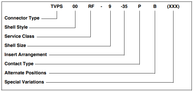
Connector Type
- TV: designates Tri-Start Series Connector
- TVP: designates back panel mounted receptacle
- TVS: designates 200°C rated
- TVPS: designates back panel mounted 200°C rated receptacle
Shell Style
- 00: designates wall mount receptacle
- 01: designates line receptacle
- 02: designates box mount receptacle
- 06: designates straight plug
- 26: designates proprietary CLUTCH-LOK high vibration straight plug (available in service classes RK and RS only)
- 07: designates jam nut receptacle
- 09: designates flange mounted plug
- IY: designates solder mounted receptacle (hermetic only)
- HIY: designates weld mounted receptacle (hermetic only)
Service Class
- RX: alternate finish (special suffix required)
- RF: electroless nickel plated aluminum (200°C)
- RGF**: electroless nickel plated ground plane aluminum (200°C)
- RGW**: olive drab cadmium plated ground plane aluminum (175°C)
- RK*: corrosion resistant stainless steel (200°C)
- RW: corrosion resistant olive drab cadmium plate aluminum (175°C)
- RQF: same as RF with Quadrax contacts
- RGQF: same as RGF with Quadrax contacts
- RGQW: same as RGW with Quadrax contacts
- RQK: same as RK with Quadrax contacts (not firewall capable)
- RQW: same as RW with Quadrax contacts
- Y: hermetic seal passivated stainless steel (200°C)
- RS*: nickel plated stainless steel (200°C)
- YN: nickel plated stainless steel (hermetic connectors) (200°C)
- DN: Durmalon plated (Nickel-PTFE)
Shell Size
MIL-DTL-38999 Sizes 9-25
| A | B | C | D | E | F | G | H | J |
|---|---|---|---|---|---|---|---|---|
| 9 | 11 | 13 | 15 | 17 | 19 | 21 | 23 | 25 |
Insert Arrangement
MIL-DTL-38999, see insert arrangement charts in catalog 12-C3
Contact Type
- P: designates pin contacts
- S: designates socket contacts
Alternate Positions
Locksmith keying - rotation of minor keys. See catalog 12-C3 “N” not required for normal position.
Special Variations
Consult Amphenol Aerospace Sidney NY for variations.
* Coaxial arrangements are not available in these classes.
** For more information on Coax/Triax/Twinax Ground Plane Connectors consult Amphenol Aerospace.
NOTE:
Catalog 12-C3 catalog was released Jan. 2010. It covers the majority of the circular connector products offered by Amphenol Aerospace. Go online for this catalog at www.amphenol-aerospace.com, where the product sections can be viewed and downloaded. The next version of this combined circular product catalog (12-C4) will be available within 2011. Consult Amphenol Aerospace, Sidney NY for more information.
Subminiature Tri-Start
How to Order – D38999, TV Military, metal and MTV26 CLUTCH-LOK®
Proprietary Part Number
Amphenol® Tri-Start Connectors (metal) can be ordered by coded part number
Ordering procedure is illustrated by part number TVPS00RF-9-35PB( ) as shown below:
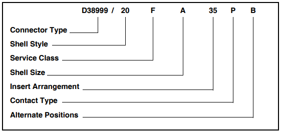
Connector Type
- D38999/: designates MIL-DTL-38999 Series III Connector
- MTV: designates military D38999/26 CLUTCH-LOK high vibration straight plug (available in service class RK only)
Shell Style
- 20 designates wall mount receptacle
- 21 designates box mount receptacle, hermetic
- 23 designates jam nut receptacle, hermetic
- 24 designates jam nut receptacle
- 25 designates solder mount receptacle, hermetic
- 26 designates straight plug
- 27 designates weld mount receptacle, hermetic
- 29 designates Lanyard Release plug with pin contacts*
- 30 designates Lanyard Release plug with socket contacts*
- 31 designates Lanyard Release plug with MIL-STD-1760 pin contacts*
*For ordering Amphenol® Lanyard Release Connectors, consult catalog 12-C1. Specify lanyard length codes and designate Style 1 or 2.
Protection Caps (see catalog 12-C3)
- 32 designates plug protection cap
- 33 designates receptacle protection cap
Service Class
- C non-conductive, anodic coated aluminum, 500 hour salt spray, 200°C (environmental resisting)
- F electroless nickel plated aluminum, optimum EMI shielding effectiveness – 65dB @ 10GHz specification min., 48 hour salt spray, 200°C (conductive, environmental resisting)
- G space grade, electroless nickel, 48 hour salt spray, 200°C
- K corrosion resistant stainless steel, firewall capability, plus 500 hour salt spray resistance, EMI – 45 dB @ 10 GHz specification min., 200 °C
- L corrosion resistant steel, electro-deposited nickel, 48 hour salt spray, 200°C
- W corrosion resistant olive drab cadmium plate aluminum, 500 hour extended salt spray, EMI – 50 dB @ 10GHz specification min., 175°C
- Y hermetic seal, passivated stainless steel, 200°C
- S (non-hermetic connectors), nickel plated stainless steel, optimum EMI shielding effectiveness – 65 dB @10 GHz specification min., 48 hour salt spray, 200 °C
- N (hermetic connectors), nickel plated stainless steel, 200 °C
Shell Size
MIL-DTL-38999, Size 9 – 25
| A | B | C | D | E | F | G | H | J | MIL Shell Size |
|---|---|---|---|---|---|---|---|---|---|
| 9 | 11 | 13 | 15 | 17 | 19 | 21 | 23 | 25 | Amphenol® Shell Size |
Insert Arrangement
MIL-DTL-38999, see catalog 12-C3
Contact Type
- P Designates pin contacts
- S Designates socket contacts
- A designates same as “P” except supplied less pin contacts
- B designates same as “S” except supplied less socket contacts (A & B designates non-standard contact applications)
- X designates eyelet contacts, hermetics only
Alternate Positions
Locksmith keying - rotation of minor keys. See catalog 12-C3. Use “N” for normal position.
Special Variations
Consult Amphenol Aerospace Sidney NY for variations.
Amphenol® Cage Code: 77820
Subminiature Tri-Start
How to Order –Amphenol® CTV, composite
Proprietary Part Number
Amphenol® Tri-Start Composite Connectors can be ordered by coded part number.
Ordering procedure is illustrated by part number CTVPS00RF-9-35PB as shown below:
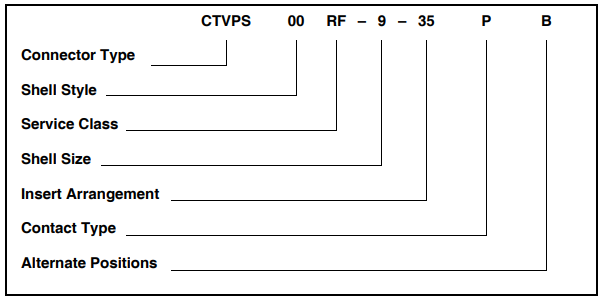
Connector Type
- CTV designates Tri-Start Series Connector
- CTVP designates panel mounted receptacle
- CTVS designates 200°C rated
- CTVPS designates panel mounted 200°C rated receptacle
Shell Style
- 00 designates wall mount receptacle
- 01 designates line receptacle
- 02 designates box mount receptacle*
- 06 designates straight plug
- 07 designates jam nut receptacle
Service Class
- RF Electroless nickel plated composite (200°C, 2000-hour salt spray)
- RW Olive drab cadmium plated composite (175°C)
- RGF** Electroless nickel plated ground plane composite (200°C)
- RGW** Olive drab cadmium plated ground plane composite (175°C)
- RQF Same as RF composite, with Quadrax contacts
- RQW Same as RW composite, with Quadrax contacts
- RGQF Same as RGF composite, with Quadrax contacts
- RGQW Same as RGW composite, with Quadrax contacts
- DN Durmalon plated, Nickel-PTFE alternative to Cadmium. Corrosion resistant, 1,000 hour salt spray, EMI-50dB at 10GHz specification min., 175 degrees
Shell Size
9 thru 25 available
Insert Arrangement
MIL-DTL-38999, see catalog 12-C3
Contact Type
- H designates 1500 cycle pin contacts
- J designates 1500 cycle socket contacts
- P designates 500 cycle pin contacts
- S designates 500 cycle socket contacts
Alternate Positions
Locksmith keying - rotation of minor keys. See catalog 12-C3. “N” not required for normal position.
* Consult Amphenol Aerospace Sidney NY for availability.
** For more information on Coax/Triax/Twinax Ground Plane Connectors consult Amphenol Aerospace
Amphenol® Cage Code: 77820
NOTE: Catalog 12-C3 catalog was released Jan. 2010. It covers the majority of the circular connector products offered by Amphenol Aerospace. Go online for this catalog at www.amphenol-aerospace.com, where the product sections can be viewed and downloaded. The next version of this combined circular product catalog (12-C4) will be available within 2011. Consult Amphenol Aerospace, Sidney NY for more information.
Subminiature Tri-Start
How to Order –D38999, CTV military, composite
Military Part Number
To more easily illustrate ordering procedure of Tri-Start Composite Connectors by military designation, part number D38999/20JG35PN is shown as follows:
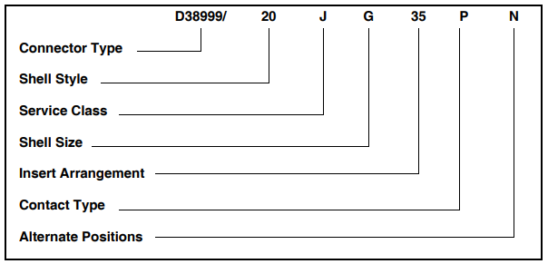
Connector Type
- D38999/: Designates MIL-DTL-38999 Series III Connector
Shell Style
- 20 designates wall mount receptacle
- 24 designates jam nut receptacle
- 26 designates straight plug
Consult Amphenol Aerospace for availability of composite box mount receptacles
Service Class
- J Olive drab cadmium plate (175°C), 2000 hrs. dynamic salt spray
- M Electroless nickel plate (200°C), 2000 hrs. dynamic salt spray
Shell Size
MIL-DTL-38999, Sizes 9-25
| A | B | C | D | E | F | G | H | J | MIL Shell Size |
|---|---|---|---|---|---|---|---|---|---|
| 9 | 11 | 13 | 15 | 17 | 19 | 21 | 23 | 25 | Amphenol ® Shell Size |
Insert Arrangement
MIL-DTL-38999, see catalog 12-C3
Contact Type
- H designates 1500 cycle pin contacts
- J designates 1500 cycle socket contacts
- P designates 500 cycle pin contacts
- S designates 500 cycle socket contacts
- A designates same as “P” except supplied less pin contacts
- B designates same as “S” except supplied less socket contacts (A & B designate non-standard contact applications)
Alternate Positions
Locksmith keying - rotation of minor keys. See catalog 12-C3 (Use “N” for normal position).
Subminiature Tri-Start
Specifications
MIL-DTL-38999 Series III (TV)
- 100% scoop-proof
- High density contact arrangements
- Contact sizes 12 through 22D plus size 8, 12, 16 coax, and size 8 twinax
- Removable crimp, PCB, wire wrap, coax, triax, twinax, and high-speed quadrax and differential twinax contacts
- Fiber optics available with MIL-PRF-29504 termini, MT ferrule termini, and ARINC 801 termini
- Options include Hermetics, Filters, and Thermocouples
- Self-locking quick disconnect threaded coupling
- Corrosion resistant - shells of stainless steel or cadmium plate over nickel withstand a 500-hour salt spray exposure
- Moisture resistance - improved interfacial seal design prevents electrolytic erosion of contacts
- EMI shielding - designed to obtain metal-to-metal coupling, the TV connector provides a superior EMI shielding capability
- Vibration/Shock - operates under severe high-temperature shock and vibration testing through 200°C
- Clutch-LokTM MIL-DTL-38999 Series III High Vibration Connector - All advantages of stainless steel/Class K firewall TriStart connectors plus a unique clutch design that actually tightens itself under vibration
- Firewall capability - available in stainless steel shell (Class K)
- Composite Tri-Start, qualified to MIL-DTL-38999, Rev. J - offers a lightweight, corrosion resistant connector with the same high performance features as it’s metal counterpart
- Lightweight: 17%-70% weight savings
- Corrosion resistance: withstands 2000 hrs. of salt spray exposure
- Durability: 1500 connector couplings
- Locksmith keying - 5 keyway polarization with 5 alternate rotations
- Shell grounding fingers are standard on all plugs
- Triple-web grommet seal
- DOD preferred
- Available in a Fail Safe Lanyard Release plug
- See catalog 12-C3
Catalog 12-C3 catalog was released Jan. 2010. It covers the majority of the circular connector products offered by Amphenol Aerospace. Go online for this catalog at www.amphenol-aerospace.com, where the product sections can be viewed and downloaded. The next version of this combined circular product catalog (12-C4) will be available within 2011. Consult Amphenol Aerospace, Sidney NY for more information.
CONTACT RATING
| Contact Size | Test Current | Maximum Millivolt Drop* | ||
|---|---|---|---|---|
| Crimp | Hermetic | Crimp | Hermetic | |
| 22D | 5 | 3 | 73 | 85 |
| 20 | 7.5 | 5 | 55 | 60 |
| 16 | 13 | 10 | 49 | 85 |
| 12 | 23 | 17 | 42 | 85 |
| 10 (Power) | 33 | NA | 33 | NA |
*Maximum Millivolt Drop data is determined by measuring the resistance of mated contacts from end to end.
** When using silver plated wire
FINISH DATA
| Non-Hermetic Shell Components | ||
|---|---|---|
| Finish | Service Class | |
| Military | Proprietary | |
| Anodic Coating (Non-Conductive) | C | RX*** |
| Electroless Nickel | F | RF |
| Olive Drab Cadmium Plate Nickel Base | W | RW |
| Stainless Steel with Nickel Plate | S | RS |
| Stainless Steel | K | RK |
| Olive Drab Cadmium Plate Composite | J | RW |
| Electroless Nickel Plate Composite | M | RF |
| Hermetic Connectors | ||
| Material/Finish | Suffix | |
| Military | Proprietary | |
| Stainless Steel | Y | Y |
| Stainless Steel, Nickel Plate | N | YN |
*** Add suffix (005) to part number
Service Rating
| Service Rating | Suggested Operating Voltage (Sea Level) | Test Voltage(Sea Level) | Test Voltage 50,000 Ft. | Test Voltage 70,000 Ft. | Test Voltage 110,000 Ft. | |
|---|---|---|---|---|---|---|
| AC (RMS) | DC | |||||
| M | 400 | 550 | 1300 VRMS | 550 VRMS | 350 VRMS | 200 VRMS |
| N | 300 | 450 | 1000 VRMS | 400 VRMS | 260 VRMS | 200 VRMS |
| I | 600 | 850 | 1800 VRMS | 600 VRMS | 400 VRMS | 200 VRMS |
| II | 900 | 1250 | 2300 VRMS | 800 VRMS | 500 VRMS | 200 VRMS |
Please note that the establishment of electrical safety factors is left entirely in the designer’s hands, since he is in the best position to know what peak voltages, switching surges, transients, etc. can be expected in a particular circuit.
Subminiature SJT
Features, Part Number Breakdown
- 100% scoop-proof – Basic LJT lengths
- Basic JT mounting dimensions
- Bayonet coupling
- 5 key/keyway polarization with 4 alternate keyings
- Rear release crimp contacts
- PCB, wire wrap, twinax, and coax contacts available
- High density insert patterns available
- Shell grounding fingers are an option on the plug
- Options include Hermetics, Filters, and Thermocouples
- See SJT section of catalog 12-C3.
SJT How to Order
PART NUMBER
To more easily illustrate ordering procedure, part number SJT00RT-18-66PA( ) is shown as follows:

See code below:
- Connector Type
- SJT designates standard scoop-proof Junior Tri-Lock Connector
- SJTS designates high temperature connector
- SJTG designates plug with grounding fingers
- SJTP designates back panel mounted
- Shell Style
- 00 designates wall mount receptacle
- 06 designates straight plug
- 07 designates jam nut receptacle
- I designates solder mount receptacle – hermetic
- Service Class
- "Y": For hermetic applications with fused compression glass sealed inserts. Leakage rate less than 0.01 micron cu. ft./hr. at 15 psi differential.
- "RT": For environmental applications - supplied without rear accessories. Serrations on rear threads of shells.
For additional information defining complete description of service class, consult Amphenol, Sidney, NY.
- SJT shell sizes available from 8 through 24.
- – 66 designates insert arrangement
- P designates pin contacts; S for socket contacts
- A designates a rotated connector assembly (alternate keying). Other basic rotations are B, C and D. No letter required for normal, (no rotation) position
- Finish variation suffix
