As the shift to more-electric and all-electric aircraft accelerates, so too does the need to dramatically reduce airframe weight. Many commercial and military aircraft already have significant portions of their bodies constructed of advanced carbon composite materials, but the proliferation of this technology is still an aircraft manufacturer’s single-greatest opportunity for further weight reduction. Though composites offer many performance advantages over traditional metal materials, the industry has yet to develop a composite material with shielding properties equal to that of their metal equivalents. Which means – now more than ever – the sensitive electronic equipment within aircraft are susceptible to transient voltage events. Transient voltage suppression (TVS) devices, which is a general classification of an array of devices that are designed to react to sudden overvoltage conditions, have become the popular choice for protection of sensitive downstream components. At Amphenol Aerospace’s Lightning Lab, we have decades of experience in packaging these devices inside of our industry-leading aerospace interconnect, saving you cost, weight, and design time.
What is Transient Voltage?
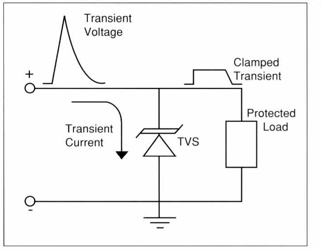
Transient voltages are voltage spikes that are caused by a sudden release of stored energy over a short period of time. One of the more common sources of transient voltages are from lightning strikes, especially when the operating conditions of the equipment are more prone to lightning, such as airborne applications. Similar to lightning strikes, these voltage transients happen very suddenly and last only a few microseconds. Voltage transients can be particularly harmful to sensitive circuits that aren’t designed to withstand such voltage spikes.
Amphenol's Lightning Protection and Transient Voltage Suppression Technology
In addition to proven filtering capabilities, Amphenol offers superior transient voltage protection from numerous threats, including direct or indirect lightning strikes. Amphenol’s transient voltage protection connectors combine the traditional environmental protections of our standard connector products with transient voltage protection to meet all aircraft performance requirements. This technology can be a standalone component inside the connector or be coupled with additional filtering components to provide both filtering and transient protection capabilities in the same package. Amphenol transient protection connectors offer optimal weight and space saving capabilities while increasing reliability as no additional downstream circuits are required.

How do Transient Voltage Suppressors Work?
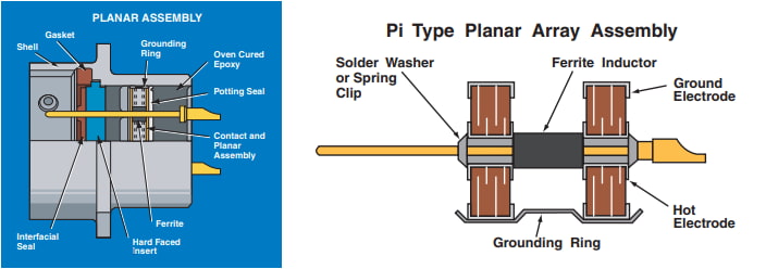
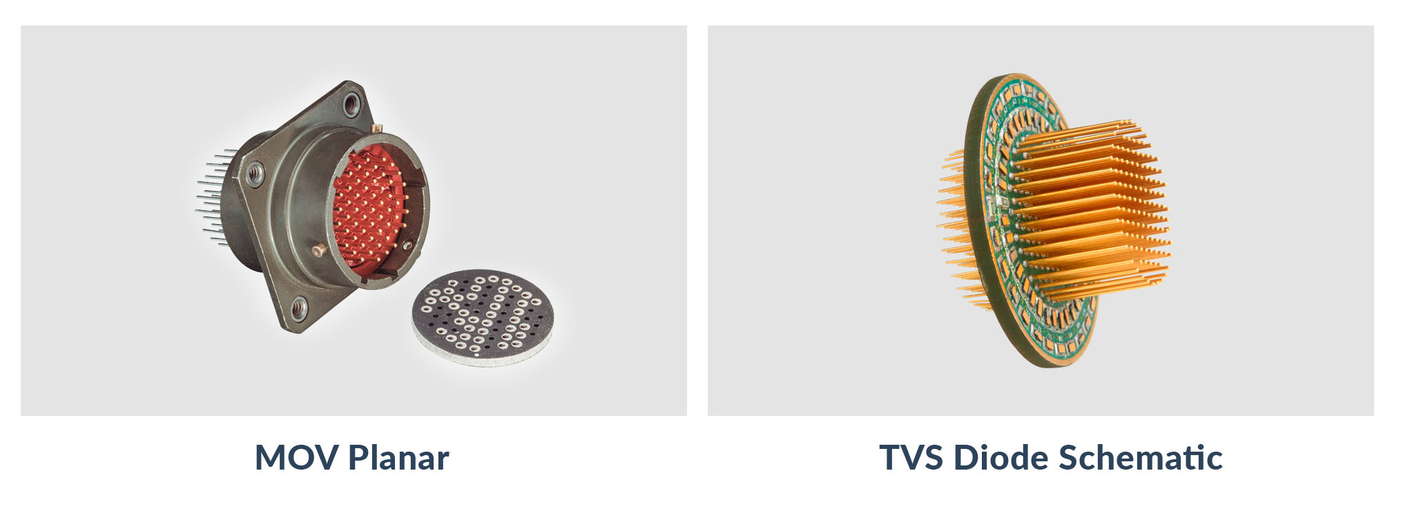
The Amphenol transient voltage protection connector utilizes the design and framework of numerous MIL-Spec connectors to preserve intermateability within the connector class while also maintaining many qualification requirements. Transient protection is achieved by utilizing passive components to clamp voltage spikes to protect sensitive downstream circuits. Amphenol offers two distinct component types to achieve this protection in the form of MOV (Metal Oxide Varisitor) planar and TVS (Transient Voltage Suppression) diodes. These components are strategically chosen to offer the optimal solution given the application requirements, and their advantages are explained below. Once the components are chosen, mechanical design considerations are taken into account to install these passive components into the connector shell while maintaining connector intermateability.
![]()
What is the Difference Between a MOV Planar and a TVS Diode?

Amphenol Aerospace primarily utilizes either MOV planar technology or board-mounted TVS diodes to accomplish transient suppression. Both devices are designed to fulfill similar electrical requirements. The MOV planar accomplishes this by installing a ceramic mass composed of metal oxide grains in between two metal electrode plates. Board mounted TVS diodes are comprised of standard semiconductor diodes mounted to a ceramic board.
Both protection devices offer nanosecond transient clamping response time, ensuring reliable protection of components. A breakdown of the advantages and disadvantages of each suppression device can be seen below.
| Protection Device | MOV Planar | TVS Diode |
| Energy Suppression | Higher | Lower |
| Clamping Voltage | Higher | Lower |
| Polarity | Bipolar Only | Unipolar and Bipolar |
| Capacitance | 1nF to 4nF | 100pF to 3nF |
| Standoff Voltage | Medium to High | Low to Medium |
| Leakage Current | Higher | Lower |
| Screening | Limited | Extensive (TX/TXV/S) |
| Contact Sizes | 16, 20, 22 | 20, 22 |
| Cost | Lower | Higher |

What Connector Series are Compatible with Transient Voltage Supression/Lightning Protection Technology?
The Amphenol transient voltage protection connector are offered popularly in any style connector and can be made in accordance with the below MIL-Specs and more:
• MIL-DTL-5015
• MIL-DTL-26482
• MIL-DTL-26500
• MIL-DTL-27599
• MIL-DTL-38999
• MIL-DTL-83723
Protection devices can be designed into plugs, receptacles, or adapters. Adapters are a convenient and economical method of introducing transient and/or filtering protection into an installed system by offering a connector with a plug mating interface on one end and a receptacle interface on the other to mate with preexisting plug and receptacle infrastructure.
How are Amphenol's Lightning Protection Products Qualified and Tested?
Amphenol Aerospace can meet the applicable transient protection profiles for lightning strikes as outlined in RTCA-DO-160G and MIL-STD-461G. After a quick consultation, Amphenol’s Lightning Lab will recommend the optimal transient protection solution given any requirement or threat environment. With industry-leading quality systems and testing requirements, Amphenol Aerospace ensures a compliant and reliable product, every time. All TVS diodes are screened to the applicable requirements of MIL-S-19500TX/TXV.
MOV Performance Characteristics
| Designation | Contact Size | Maximum Rating (125°C) | Specifications (25°C) | Maximum Leakage Current at Vt (dc) | ||||||||||
| Continuous | Transient | Varistor Voltage at 1mA (DC) | Maximum Clamping Voltage Vc at Test Current Ip (8/20μS) | Capacitance at 1MHz | IL Max. | IL Max. | ||||||||
| DC Voltage | RMS Voltage | Energy (10/1000μS) | Peak Current (8/20μS) | Picofarads | 25°C | 125°C | ||||||||
| Vm Volts | Vm Volts | Wtm Joules | Itm Amperes | Min. Volts | Nominal Volts | Max. Volts | Vc Volts | Ip Amps | Min. | Max. | μA | μA | ||
| F8 | 22 | 8 | 5.6 | 1.2 | 250 | 12 | 14 | 17 | 28 | 10 | 1000 | 2500 | 5 | 50 |
| 20 | 1.3 | 300 | 10 | |||||||||||
| 16 | 1.5 | 350 | 20 | |||||||||||
| F14 | 22 | 14 | 10 | 1.2 | 250 | 18.5 | 22 | 25 | 40 | 10 | 800 | 2000 | 5 | 50 |
| 20 | 1.5 | 300 | 10 | |||||||||||
| 16 | 1.5 | 350 | 20 | |||||||||||
| F31 | 22 | 31 | 22 | 1.5 | 250 | 35 | 39 | 45 | 80 | 5 | 400 | 1400 | 5 | 50 |
| 20 | 2 | 300 | 10 | |||||||||||
| 16 | 2 | 350 | 20 | |||||||||||
| F38 | 22 | 38 | 27 | 1.5 | 250 | 42 | 47 | 55 | 90 | 5 | 200 | 1000 | 5 | 50 |
| 20 | 2 | 300 | 10 | |||||||||||
| 16 | 2.5 | 350 | 20 | |||||||||||
| F45 | 22 | 45 | 32 | 1.5 | 250 | 53 | 59 | 68 | 100 | 5 | 200 | 850 | 5 | 50 |
| 20 | 2.5 | 300 | 10 | |||||||||||
| 16 | 3 | 350 | 20 | |||||||||||
NOTE: Continuous voltage ratings are based on 1000 hour reliability assurance tests at 125°C rated ambient temperature per MIL-STD-202 method 108. Contact Amphenol Sidney for options not listed in chart.
For more information contact Brennen Levis at Filterapps@amphenol-aao.com
