LRM - Line Replaceable Module
Contact:
Description:
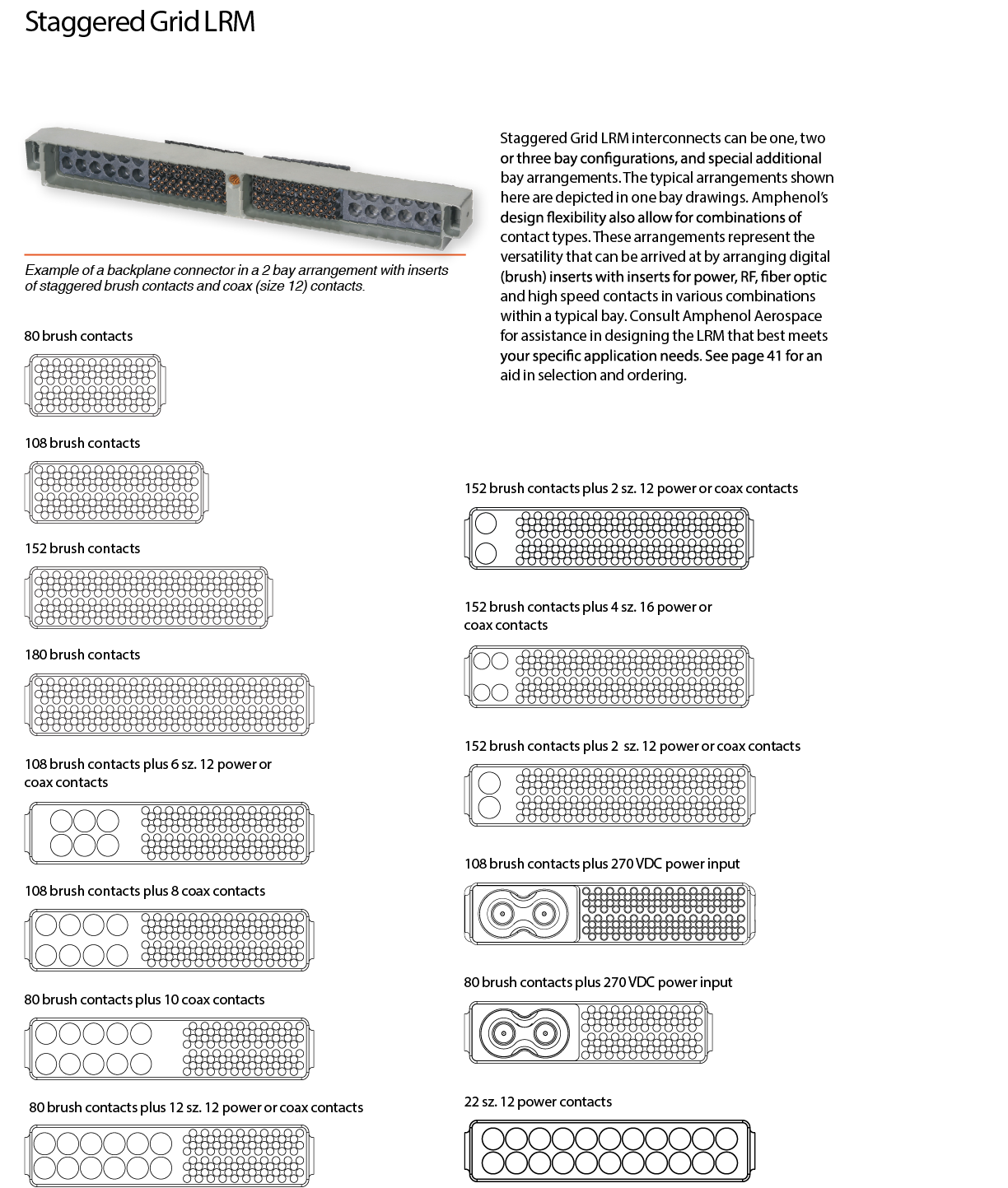
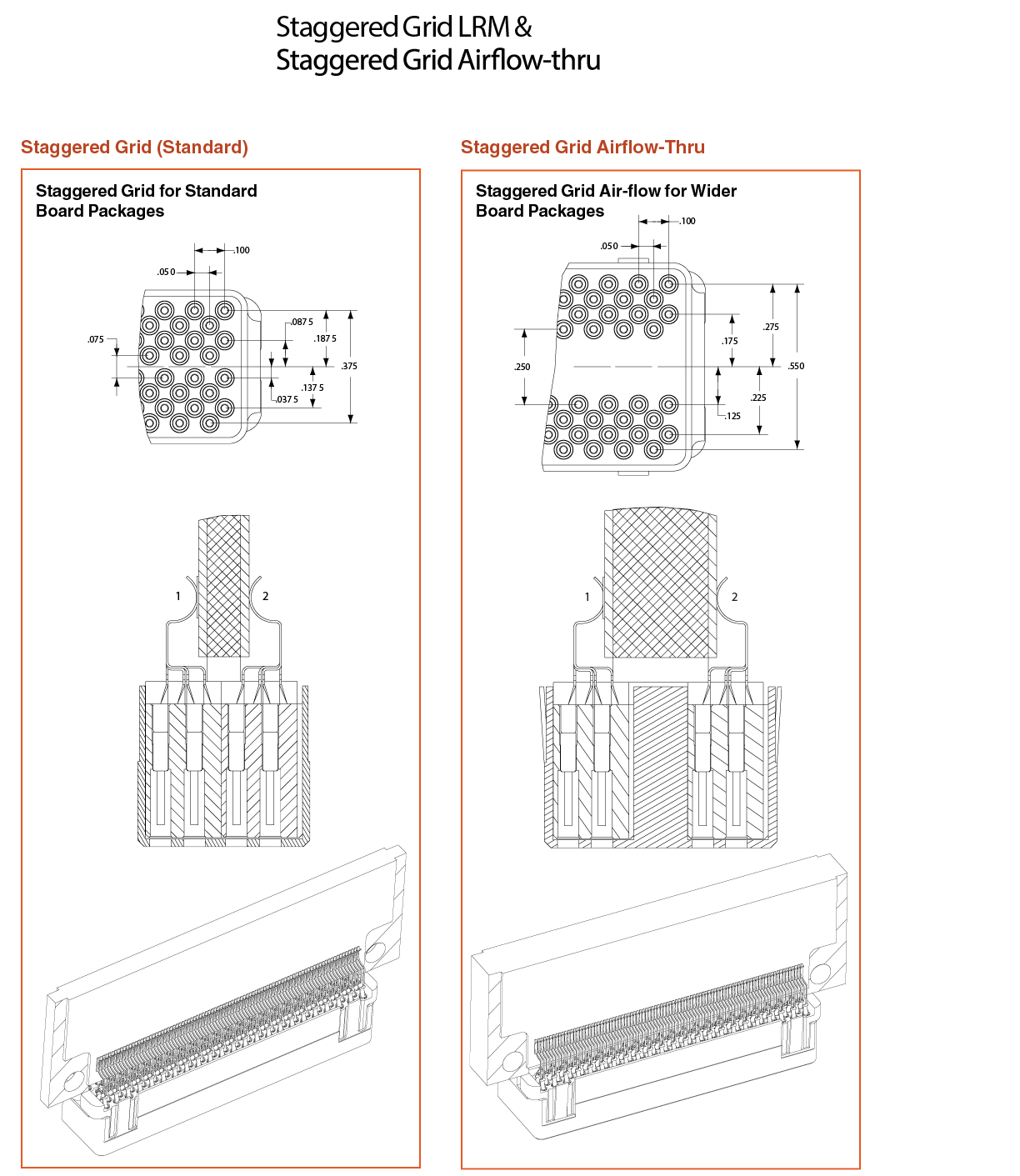
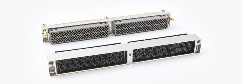
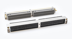
LRM surface mount connectors meet the high density needs of today’s integrated electronic modules. The flexibility in design allows Amphenol to meet and exceed the wide variety of user requirements. With multiple different contacts being used in the connectors, mainly digital (brush), there are thousands of combinations of inserts that are possible. These different configurations are all tailored to meet the needs of the customer.
The utilization of Brush contacts with low mating force, ESD shields for Level II Maintenance and lateral float for ultimate cold wall heat dissipation make this board-to-board mating scheme the best solution for ruggedized chassis.
Features & Benefits:
- Available in SEM-E and custom form factors
- B3 Brush contact – Provides low mating force, multiple points of contact, stable electrical performance and extended service life
- ESD Protection (Module Connector)
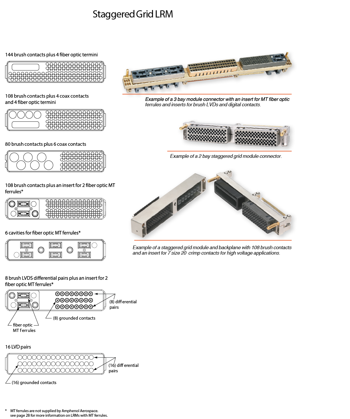
- Can be designed in 1, 2 & 3 bay configurations with many shell designs available.
- Surface mount termination (Module Connector)
- PCB or Compliant termination (Backplane Connector)
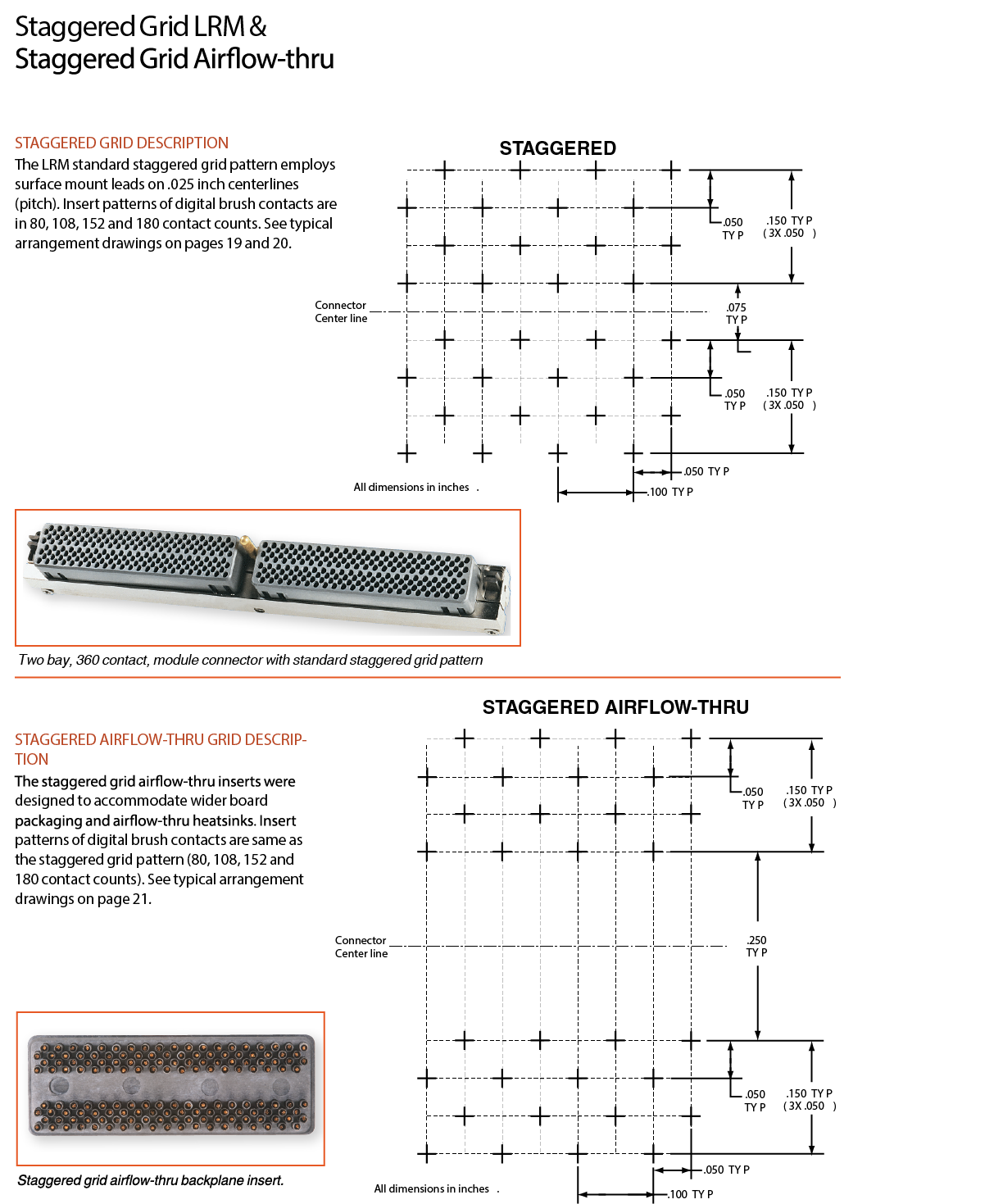
- Typical standard arrangements of Digital (Brush) inserts – 80, 108, 152 & 180 pins
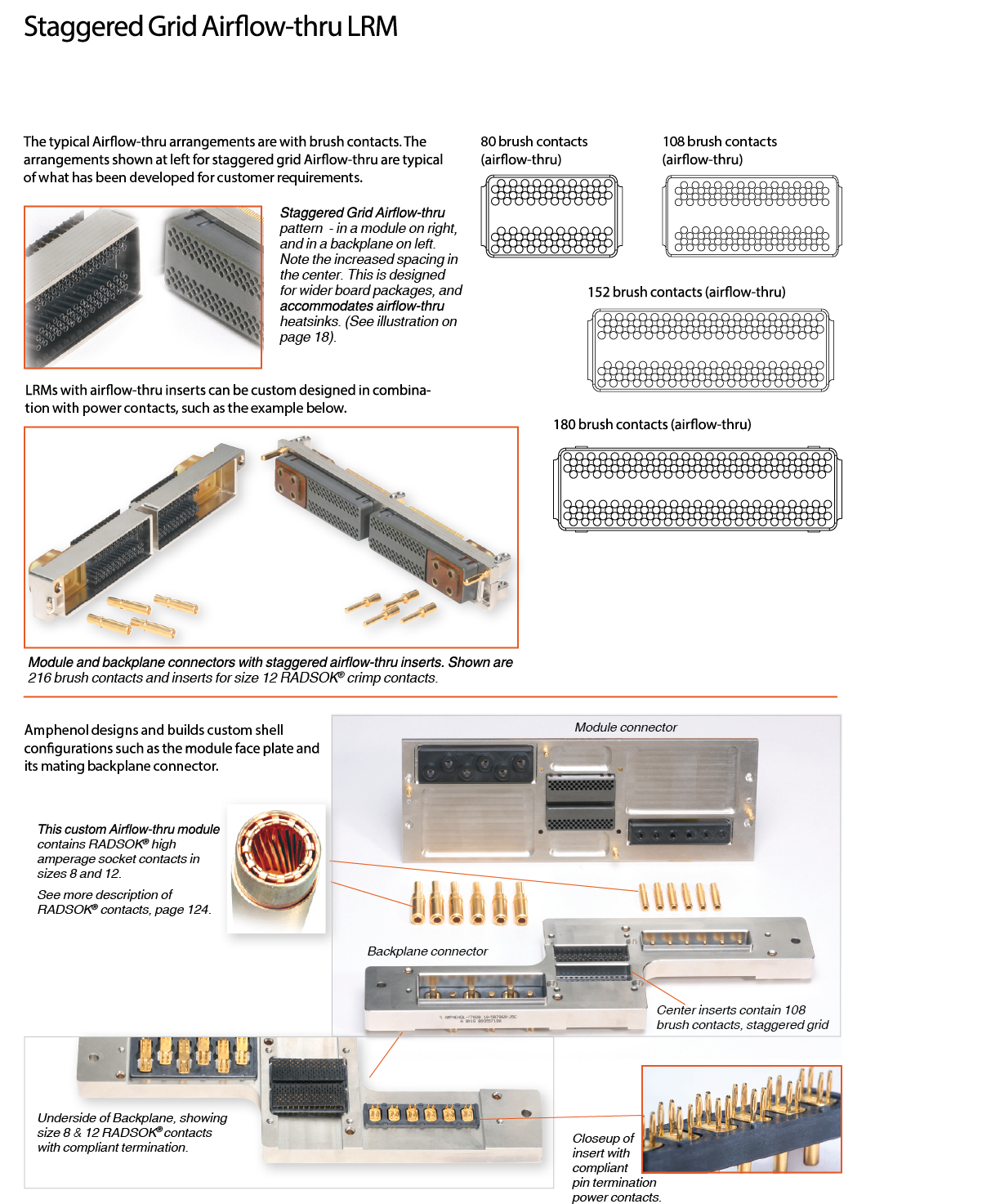
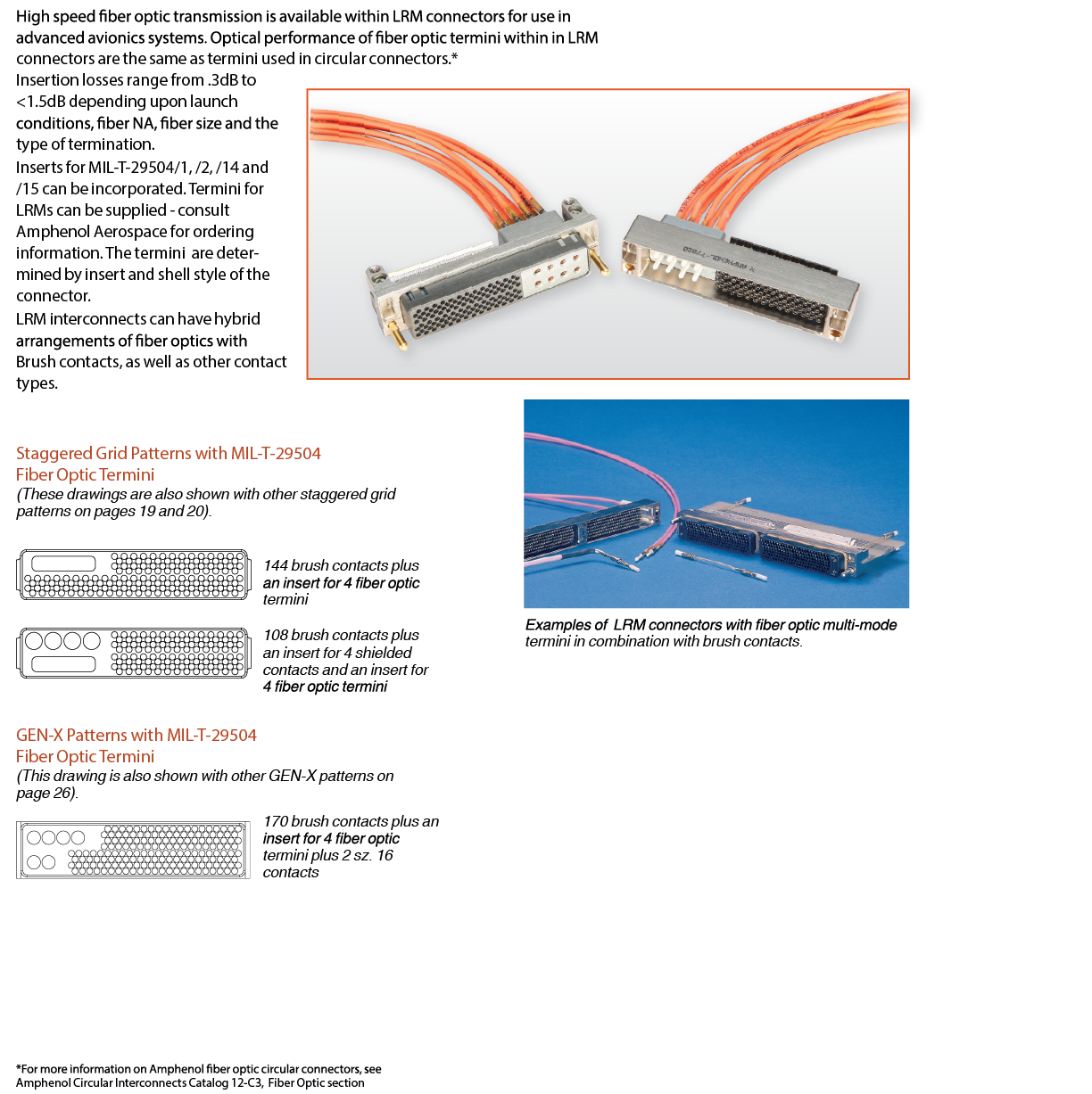
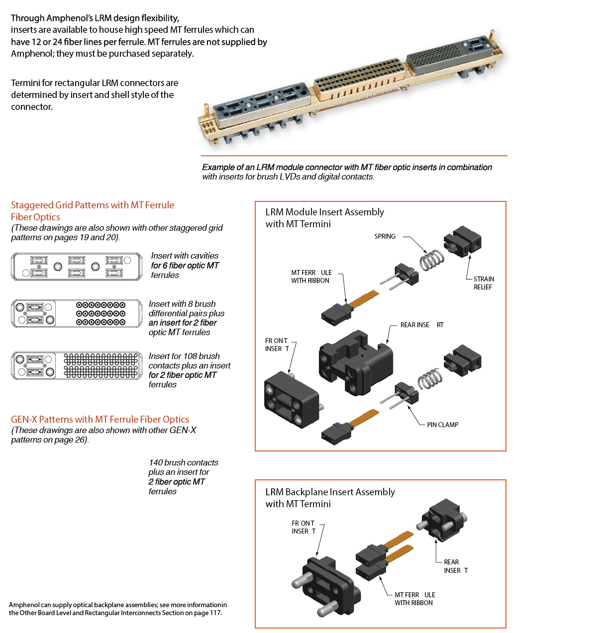
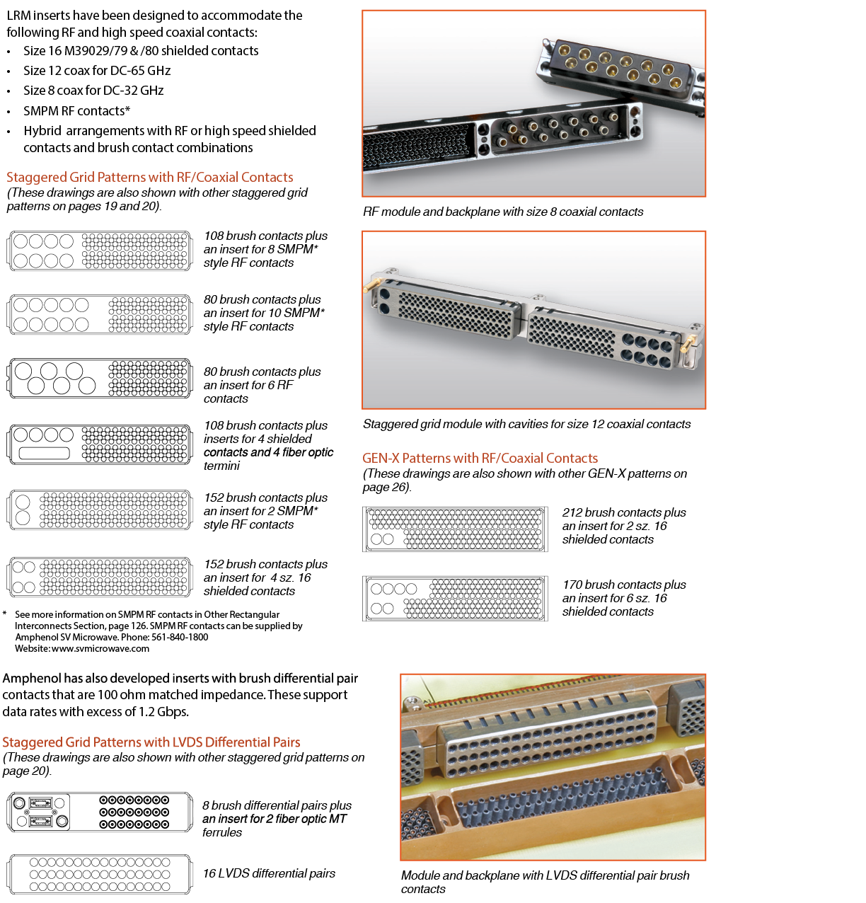
- Inserts for power, RF, fiber optic and high speed contacts are also available
Electrical Performance
| Electrical Parameters | Performance |
| Current carrying capability | 10°C temperature rise at 2A and 30°C rise at 3A |
| Contact resistance | 30 milliohms max. per contact, 25 milliohms max. average |
| Dielectric withstanding voltage at sea level | 100 VRMS, 60 Hz |
| Dielectric withstanding voltage at altitude | 100 VRMS, 60Hz at 70,000ft. |
| Insulation Resistance | 1000 megohm minimum at 100V d.c. |
| Electrostatic Discharge Protection (module only) | ±25,000 minimum air and direct discharge |
Mechanical Performance
| Mechanical Parameters | Performance |
| Contact retention (solder type backplane assembly) | Maximum displacement of 0.010" at 1 pound load |
| Mating and unmating forces | Maximum 40.0 pounds mating and unmating |
| Vibration (Sinusoidal, 20g peak max.) | No electrical discontinuity >1μS |
| Vibration (Random, 11.6g RMS max.) | No electrical discontinuity >1μS |
| Shock (50g max. shock pulse) | No electrical discontinuity >1μS |
| Solderability | Minimum 95% solder coverage |
| Resistance to soldering heat | 260°C dip for 10 seconds |
Environmental Performance
| Mechanical Parameters | Performance |
| Temperature life | 250 hours at 125°C maximum |
| Connector durability | 500 cycles mating and unmating |
| Salt fog exposure | 48 hours maximum direct exposure (5% NaCl) |
| Thermal shock | 500 cycles at +125°C / –65°C |
| Humidity exposure | 240 hours at 90 - 98% |
| Contamination exposure | Sand and dust per MIL-STD-202 Method 110 |
| Resistance to solvents | Boiling Trichloroethylene fumes and solution |
Environmental Performance
| Part | Material / Finish Description |
| Brush wires |
Beryllium copper; finish is gold over nickel (The exposed ends of the brush wires need not be plated). |
| Module contacts |
Beryllium copper; finish on contact body is matte tin-lead; finish on termination end is 60/40 or 63/37 tin-lead dip |
| Backplane contacts (Compliant termination) |
Contact barrel: brass; finish is tin-lead over nickel. |
| Backplane contacts (PCB termination) | Contact body: brass; finish is gold over nickel; termination end is 60/40 or 63/37 tin lead dip. Contact sleeve: stainless steel; finish is black oxide and conformally coated per MIL-I-46058. |
| Insulators | Polyphenylene Sulfide or Liquid Crystal Polymer. |
| Organizer | Polyphenylene Sulfide or Liquid Crystal Polymer. |
| Shells | Aluminum alloy; finish is electroless nickel. |
| ESD shields | Aluminum alloy; finish is hardcoat anodize with epoxy final coat. Ground tabs are chromate treated (irridite). |
| Polarization keys | Stainless steel; finish is black oxide. Key retaining ring is Polyamide (nylon 12) with 50% glass filled fibers. |
| Guide pins | Beryllium copper alloy; finish is gold per over nickel. |
Brush Contacts vs. Conventional Pin and Socket Contacts
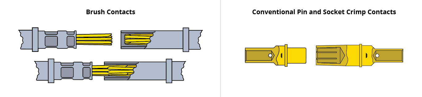
Brush Contact Innovation
- Multiple contact interfaces - Strands of high tensile wire are bundled together to form brush-like contacts. By intermeshing two multi-strand wire bundles, an electrical connection is made.
- Provides redundant current paths, 14-70 (points of contact) per mated contact with a gas-tight junction
- Very smooth (low friction) interface
Conventional Pin and Socket
- Machined surface finish on both parts
- Higher friction and wear
- Limited number of contact sites